Input Track Set

Contents
Command line: DBINGL
Ribbonbar: -
This function serves the input of track elements (track centers, track switches, crossings) in the ProSig project.
Track sets receive special treatment regarding their crosscheck mechanisms in ProSig projects.
When a drawing is added to a project, the track switches, crossings and track elements in it are not automatically input in the ProSig project. Nor are the aforesaid objects automatically input in the project data when they are inserted in a project drawing.
Activating the DBINGL function opens the following dialog:
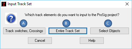
Illus.: Dialog "Input Track Set"
There are three options for track set input:
"Track Switches, Crossings" Button (A)
With this function, all track switches and crossings included in a drawing are input in the project. These objects are required for generating the safeguarding technology overview plan in particular.
"Entire Track Set" Button (B)
With this function, all track switches, crossings and track elements included in a drawing are input in the project (for filter criteria, see Notes).
"Select Objects" Button (C)
With this function, you can explicitly select track set objects for input in the ProSig project. This allows for the input of demarcated track set areas in the project.
When selecting these options, you should consider whether input of the track elements in the ProSig project is really necessary. This is because track elements generally comprise a very large number of objects. Especially with voluminous ProSig projects, this may lead to considerably slower processing speed.
Unless the track set changes in the course of a project, you can alternatively copy the track elements into other layout plans (any crosscheck using the project would prove futile.)
Notes:
Track sets can only be input in layout plans. Also, no track switches, crossings or track elements can be input in safeguarding technology overview plans.
The presentation of track switches and crossings (lines or circles at track switch beginning/center) depends on whichever directive is set when a track switch is inserted. Meanwhile, the presentation of track switches in reproduced plans depends on whichever directive is set at the time of INPUT of a track switch.
Example: A track switch INSERTED under the directive 'Bundesbahn/Fed. Railway' (circle at track switch center) but INPUT under the directive '9002' will be presented based on directive '9002' in a reproduced plan - irrespectively of whichever directive is set in the reproduced plan.
Filter criteria for the track elements are the ProSig layers for main and side tracks. Object types that are edited include lines, arcs and polylines. When editing the polylines, remember that they must be of the "LWPOLYLINE" type (optimized polylines).
Any changes to a track set once it has been input in the ProSig project requires renewed activation of the DBINGL function (at least for the area in question).
Renewed activation of the aforesaid causes only objects to be input that are not already in the ProSig project.
In all layout plans assigned to a project, the track set input is generated identically.
In the safeguarding technology layout plans, only track switches and crossings are generated in the form of their schematic presentations.
Following their input in the ProSig project, the track switches and crossings require new chainage. To this end, use the 'Update Route' function and the 'Location Determination' function for the objects of the current route. Mere input in the ROUTE attribute is NOT enough. A renewed location determination is the only way to ensure all the object attribute input necessary for crosschecking the objects in the safeguarding technology layout plan.
ProSig only supports the object types Line, Arc and LWPolyline. If a track set includes object types like Spline or 2D-Polyline, then these have to be converted into polylines as follows:
•In AutoCad 2007 to 2009, use the ProSig function Spline --> Polyline
•In AutoCad 2010 to 2012, use the AutoCad function PEDIT
Lines belonging to the object types Multiline and 3D-Polyline have to be manually replaced using LWPolylines.
Use the AutoCad command CONVERT to convert track elements of the type Polyline prior to track set input for the type LWPolyline.