Deriving further Layout Plans

Contents
Process:
•Deriving further Layout Plans
Requirements:
Description:
After the creation of the Signalling Layout plan, it is possible to create further Layout plans (e.g. Cable Layout Plan) completely autonomously in different scales from the ProSig project.
For this purpose, an empty drawing is assigned to the existing project. A blank drawing can be assigned to an existing project, provided no other drawing of this project is open.
When defining the drawing attributes Plan type and Scale, it is important to check the attributes, as they cannot be changed after the integration into the project.
The Alignment of an object into another Layout plan takes place automatically. The objects are positioned according to the set scale at the corresponding location.
Procedure:
1.To assign the drawing for a Planning Project, use the function 'Project Manager'.
Command Line: PRS_PROJEKTMANAGER
Ribbon: ProSig EPU -> ProSig Project-> Project Manager
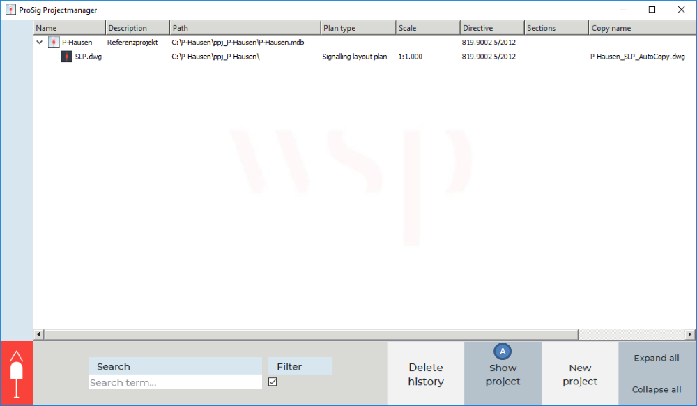
Illus.: The project manager displays a project with an assigned Signalling layout plan
oIf the project to which the drawing is assigned as an additional layout plan is not displayed in the project manager, it can be opened with the button 'Show project' (A).
2.By right-clicking on the project and selecting the menu item 'New drawing', another AutoCAD drawing can be assigned to the project.
3.Subsequently, the drawing attributes of the assigned DWG can be defined. The attributes can be entered by double-clicking with the left mouse button in the respective field.
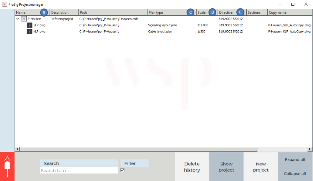
Illus.: Defining the attributes of a further Layout plan with the example of a Cable Layout Plan
oThe Attribute 'Name' (B) should be filled with the name of the drawing. If no name is entered, the name of the drawing is automatically determined when saving in accordance to the plan type defined, i.e. the name is automatically assigned as 'KLP' for the Cable Layout Plan.
oThe Attributes 'Plan type' (C), 'Scale' (D) and 'Directive' (E) for the Cable layout plan are defined accordingly via the drop-down list.
4.Subsequently, save the newly assigned drawing by right-clicking on the drawing and selecting the menu item 'Save'.
5.Open the drawing by right-clicking on the newly assigned drawing and selecting the menu item 'Open'.
oThe Objects are positioned by their X/Y coordinates according to the set scale. The Position and Alignment of the visible attributes are plan-specific attributes and therefore they are not adjusted by the ProSig project. The Attributes of the newly inserted objects retain their default position.