Import the Track Set from GND

Contents
Process:
•Importing the geographical information regarding track set from the DB-GIS
•Post-editing the track set
Requirements:
•A new ProTop project with a Signalling Layout plan, see also points 1 to 8 under Setting Up Planning Project
Description:
Geographical information regarding track set is stored in the DB-GIS of Deutsche Bahn. For the planning area to be processed, a track network database (GND-Edit exchange database) must be requested from the customer. Through the GND import interfaces, the data is imported into the ProSig project.
After importing the data, the track layout is automatically updated by breaking the tracks passing through the facing end of a point of the switches. Thereafter, it is possible to correct the connections at the facing end of points.
Supporting movie sequence:
Importieren_der_Gleislage_aus_GND.mp4 (Size 3,9 MB)
Procedure:
1.Import Track Set data from the GND Edit exchange database.
Command Line: GL_GND_IN
Ribbon: ProTop -> Track Set/Topology -> GND Track Set
oThe geographical information regarding the track set is read from the GND-Edit Exchange Database into the drawing and stored as lines and arcs on the main track layer.
oOnce the Track axes have been imported, the prompt 'Perform connection correction? (Yes/No) <Y> :' appears:
▪If the prompt is answered with 'Yes', the track set is processed as described in step 2.
Continuous tracks are automatically disrupted at the facing end of a points. The co-ordinates of the switches that have been imported from the track network database are marked and labeled with the basic switch form and the switch number. The markings and labels are stored on the layer PRS-TEMP-GND.
▪If the prompt is answered with 'No', no connection correction is performed. Continuous tracks are not disrupted at the facing end of a points. The track set is not processed as described in step 2.
2.If the correction of the connection is performed, the track set is processed according to the following use cases. An automatically generated report provides information about the corrections.
oUse case1:
▪Corrections up to 3 mm are performed automatically and are not reported in the report.
oUse casel 2:
▪Corrections between 3 mm and 5 cm are carried out automatically and reported in the report. The track elements before the correction are displayed on the layer GND-GLEIS-VOR-KORREKTUR.
▪The Automatic corrections needs to be checked.
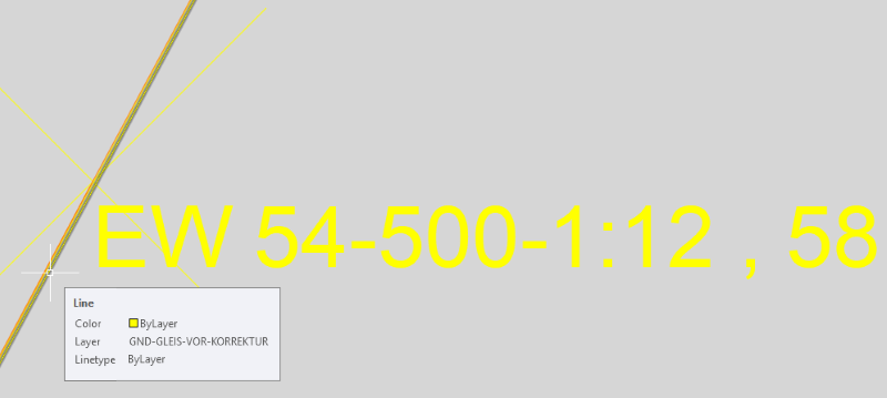
Illus.: Automatically corrected Track Set
oUse case 3:
▪Corrections from 5 cm are not carried out automatically and they will be reported in the report. The corrections need to be made manually.
▪The end points of the disrupted tracks must be dragged to the layer (layer PRS-TEMP-GND) using grips (setting the system variable GRIPS=1 or 2).
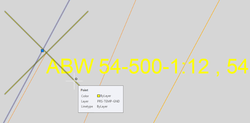
Illus.: Not automatically corrected track set, the correction needs to be done manually
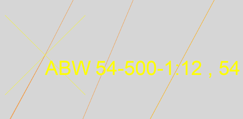
Illus.: Track Set after manual correction
3.If the branch track arcs of Single slip and Double slip are not automatically generated, they needs to be be constructed manually using the AutoCAD function 'Arc (Start Pt, End Pt, Direction)'. In the following, the process is explained using the example of a Double slip.
1.Use the 'Set Track Layer' function to set the current layer of the tracks.
Command Line: SETLAY_HG
Ribbon: ProTop -> Track Set/Topology -> Set Track Layer
2.For the lower branch arc, Start point A, End point B and the direction of Node C opposite to the start node are to be selected one after the other.
3.For the upper branch arc, Start point C, End point D and the direction of Node A opposite to the start node are to be selected one after the other.
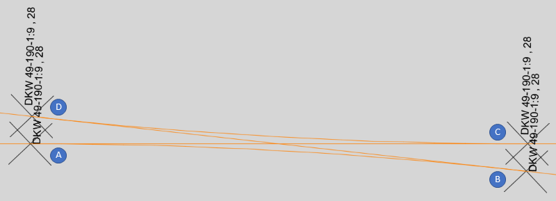
Illus.: Selection order of the nodes for the construction of branch track arcs using the example of a Double slip