Fundamentals And Principles

Contents
The Functions for the Extended Planning Unit (EPU) are based on a data model in which all elements related to safety-related are explicitly assigned to the track topology.
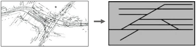
Illus.: From track set in ProSig drawings to track topology in ProSig data model
Track topology is a 'Node and edge model of possible track paths', which is produced from the ProSig-Track set and features graphic representations in drawings. These are included on a separate layer (PRS-TOPOLOGICAL EDGE, PRS-TOPOLOGICAL NODE) in the Signalling layout plan. A description of how to create the topology can be found under Creating the Topology.
Topological Nodes are branching possibilities (switches, slip switches) as well as end of tracks.
Topological Edges represent the connections between the topological nodes. A topological edge may consist of multiple track elements connected to one another.
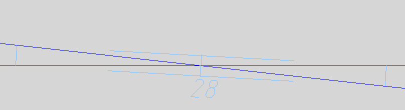
Illus.: Track set of a double slip
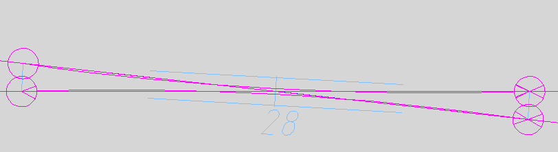
Illus.: Visual display inspection of track topology of a double slip (four nodes, four edges)
All objects have a clearly defined position in relation to this model. This means that they are assigned to an edge. For each edge, direction, beginning and end are defined. The objects receive a stationing on the edge.
The data model distinguishes between:
•Dot-like objects (example: Signal)
•Area objects (example: Track Path)
•Logical objects (example: Track Route)
Dot-like objects can be inserted according to their object type at the topological edge or in the free drawing area.
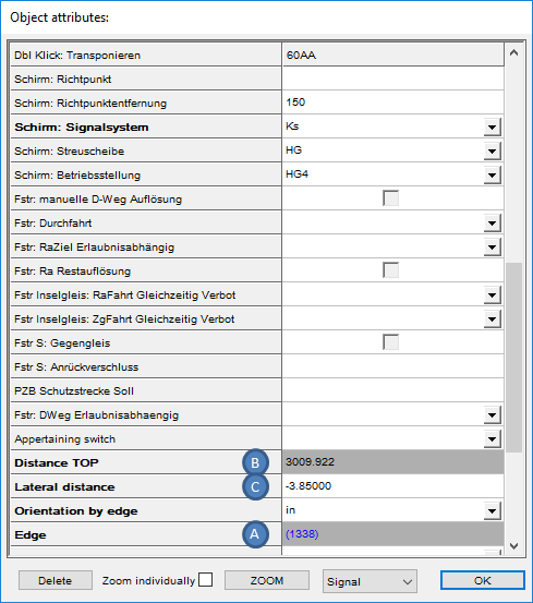
A dot-like object associated with one or more topological edges (A), has a station (B) at these edges and possibly a lateral distance (C) left or right in direction of the edge. If the object has a left lateral distance in the direction of the edge, the value for the attribute 'lateral distance' is positive; if the object has a right lateral distance, the attribute value is negative.
The objects are inserted on the topology, are automatically located during insertion and thus receive a unique position in the topological model.
A dot-like object that has no relation to the edge of the track (for example, symbols representing key dependencies) is inserted in the free drawing area. It is not assigned to a topological edge, has no station on an edge, has no lateral distance and is not located.
 |
 |
Illus.: Excerpt from the object attributes of a dot-like object (signal) located at the topological edge |
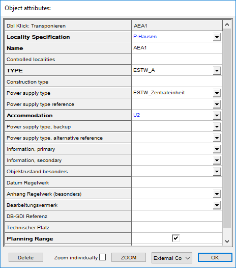
Illus.: Excerpt from the object attributes of a dot-like object (external control architecture) that was positioned in the free drawing area. |
The Area object is assigned to one or more edges (D); the respective stations (E, F) describe the section of the edge that belongs to the range. The starting point of an area object is defined as a station on an edge. The end point of an area object can be on the same edge or on another edge.
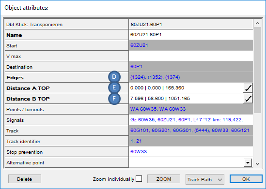
Illus.: Object attributes of an Area object (track path)
The Logical object usually represents a complex interlocking relationships and is not visualized in the drawing.

Illus.: Extract from the object attributes of a Logical object (track route)