Determining the Planning Direction

Contents
Process:
•Set the planning direction as a basis for automatic calculations.
Requirements:
Description:
The planning direction determines the chainage in the ProSig project. It should be created in such a way that it corresponds to the chainage direction of the main route of the project. In addition to the lateral distance and the working direction of an object (in reference to the topological edge), it is essential for the unique positioning of the object within the ProSig project. The planning direction is used to perform direction-dependent calculations, e.g. calculating the distance of a signal to the Fundamentvorderkante (Signalling table 1), calculating a position within the track of an FMA component (Axle counter table) or automatically calculating the designations of FMA components.
To create the planning direction, create a fictitious Chainage axis in the main view of the project the length which covers the planning area. The function 'Planning direction' enables to assign a location on the planning direction of each topological node.
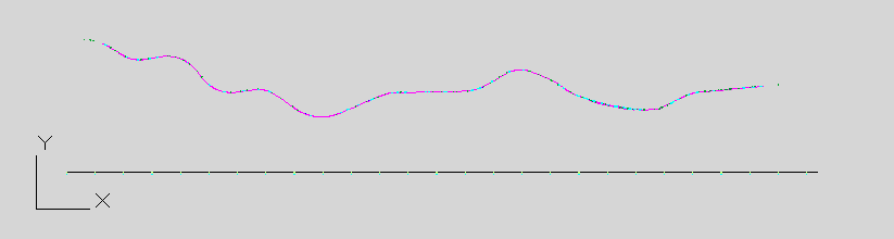
Illus.: Setting up the fictitious chainage axis to determine the Planning Direction
Supporting video sequence:
Planungsrichtung_bestimmen.mp4 (Size: 10,2 MB)
Procedure:
1.Define the main view of the project drawing. This could be for example the station area. The User Coordinate System (UCS) needs to be set accordingly.
2.The AutoCAD function PLINE is used to draw a polyline as a straight line. The length of the line should enclose the planning area in order to locate every point of the topology onto the line.
oWhen creating the polyline, you must already pay attention to the direction in which it is drawn. Later the starting point of the polyline represents the starting point for the chainage axis of the planning direction.
oSelect the starting point so that the planning direction corresponds to the chainage direction of the leading route in the ProSig project.
3. Execute the function 'EPU-Object Inserter' and create an area object 'Chainage Axis' for the planning direction.
Command Line: PRS_EPU_EINF
Ribbon: ProSig EPU -> Equipment SCT -> EPU-Object Inserter
1.The Prompt 'Choose Polyline:' appears on the command line. - The polyline created in step 2 needs to be selected.
2.At the prompt 'Strecke wählen: [Prichtung]' is displayed: Specify P for the planning direction.
3.The prompt 'Enter start kilometer:' appears on the command line. - The Start Kilometer of the planning direction needs to be specified, e.g. with the value '0.000'.
4.The prompt 'Enter end kilometer:' appears on the command line. - The End Kilometer is automatically determined based on the length of the polyline drawn in step 2 and has to be confirmed with the Enter key.
4.After the insertion of the 'Chainage Axis' object, all relevant data needs to be checked using the function Edit Object(s).
Command Line: OE
Ribbbon: ProSig EPU -> Tools -> Edit Object(s)
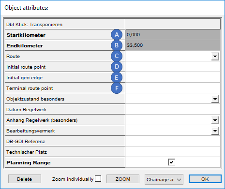
Illus.: Attributes of the chainage axis of the planning direction
oThe attribute 'Startkilometer' (A) is automatically assigned with the value specified in Step 3.3.
oThe attribute 'Endkilometer' (B) is automatically assigned with the value specified in Step 3.4.
oThe attributes 'Route' (C), 'Initial route point' (D), 'Initial geo edge' (E) and 'Terminal route point' (F) are not assigned to the chainage axis of the planning direction, as this is a fictitious chainage axis. For the planning direction, no corresponding route points and Geo-objects are created.
oAfter closing the dialog, the milestones are automatically set up to the end kilometer of the chainage axis. The distance between the milestones in the Signalling layout plan is automatically set to 100 metres.
5.The function 'Planning direction' assigns each topological node a location on the chainage axis of the planning direction.
Command Line: PRS_PLANUNGSRICHTUNG
Ribbon: ProSig EPU -> Planning Basis -> Planning Direction
6.The function Edit Object Type is used to check whether the topological nodes contain a location entry in the attribute 'Position (planning direction)'.
Command Line: PRS_OEA
Ribbon: ProSig EPU -> Tools -> Edit Object Type
oIf a location is missing, the next logical location along the planning direction can be entered manually (e.g. topological node A possess a location entry of 50, topological node B lies behind in the planning direction and there is no location: 60 can be entered for node B).