Insertion of Fouling Point Marker

Contents
Process:
•Insert the Fouling point marker into the ProSig project.
Requirements:
Description:
In ProSig, the fouling point marker is a dot-like object that is assigned to two topological edges in the drawing.
In the PlanPro glossary, the object for representing a fouling point marker is formulated as follows:
Fouling Point Marker
Point between the right and left leg of a Switch at which the clearance gauge and vehicle boundary lines of both switch legs theoretically intersect. In practice, the position of the fouling point marker is determined by surveying or routing. For higher speeds, larger distance measurements are also specified by the infrastructure manager.
In Signalling plan, longitudinal distances are related to the fouling point marker.
(Source: PlanPro Glossary)
Supporting video sequence:
Einfuegen_der_Grenzzeichen.mp4 (Size: 3,5 MB)
Procedure:
1.The Function 'Fouling Point Marker' is used to insert fouling point markers.
Command Line: PRS_GZ_EINF
Ribbon: ProSig EPU -> Planning Basis -> Switches / Crossings -> Fouling Point Marker
o'Grenzzeichenposition automatisch vorschlagen?[J/N] (Yes/No) <Y> :'
a)To automatically position the fouling point marker on a switch, enter 'Y' here. Then select the corresponding switch element. An automatic positioning can only be performed for ordinary switches, curved points or diamond crossovers. With Single slip or Double slip only a manual positioning is possible. ATTENTION: The automatic calculation is only an approximation. It should be considered as a default value. The correct fouling point marker positions can be taken from the survey or routing.
▪The Function 'Edit Project Object' is used to define the track distance of the switch legs, that is used for the automatic positioning of the following fouling point markers, see also Defining Project attributes and Pre-settings, Step 4.
b)To manually position the fouling point marker on a switch, enter 'N' here. Then the corresponding switch element and the two boundary points of the fouling point marker have to be selected on both topological edges on which the fouling point marker is to be located.
oFor the representation of the lines, the position of the fouling point marker is soldered to the topological edge. The line is drawn from the fouling point marker to the perpendicular point on the topological edge.
oThe Fouling point markers is a dot-like object and is located automatically at two topological edges during insertion. The object is stored on the layer 'PRS-SIGNAL-FOULING POINT MARKER'.
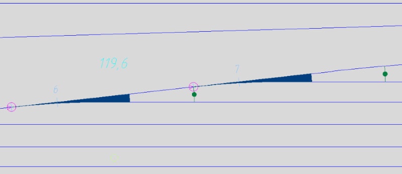
Illus.: Representation of Fouling point marker in the drawing
2.After the insertion, the function Edit Object(s) is used to verify the attributes of the fouling point marker in the drawing.
Command Line: OE
Ribbon: ProSig EPU -> Tools -> Edit Object(s)
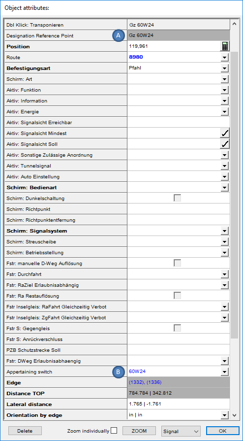
Illus.: Object Attributes of the Fouling point marker
oThe Attribute 'Designation Reference Point' (A) contains the name of the fouling point marker. The name of the fouling point marker is automatically derived from the name of the associated switch element.
oFor the Attribute 'Appertaining switch' (B), when inserting the fouling point marker, the corresponding object is automatically assigned.