Insertion of Derailers

Contents
Process:
•Insertion of Derailers into the ProSig project.
Requirements:
Description:
The Derailer is a dot-like object and in ProSig it is represented with the objects Switch Element and Switch Component. The type of the switch component is specified as the derailer device. For Derailers, the position of the derailment is located at the topology. The Derailer can be inserted as a single or double or compound derailer.
In the PlanPro glossary, an object for representing a derailer is formulated as follows:
Derailer (W_Kr_Gsp_Element and W_Kr_Gsp_Komponente)
A Derailer is a route-related interlocking element that stops a vehicle from moving through derailment before it possibly reaches a track, which needs to be protected.
In the SCT data model, all derailers are modeled with the object Switch Element.
The Derailers described here, can be designed as simple derailer (one derailer device) or as coupled derailers (two derailer devices). For the illustration and location of the derailer devices, the object Switch component is used.
The Derailers can be installed in tracks as simple derailers. Coupled derailers are installed between the switch blades and the frog of the switch to achieve a derailment direction in both switch legs in the identical direction.
For coupled derailers between frog and fouling point marker, there are no standard drawings. This construction always requires a UiG (Company internal approval) in an individual constructive solution.
Two individual derailers (not coupled) are used after a fouling point marker.
(Source: PlanPro Glossary)
Procedure:
1.Execute the function 'Derails'.
Command Line: PRS_GSP_EINF
Ribbon: ProSig EPU -> Planning Basis -> Switches / Crossings -> Derails
oWhen inserting the derailer, the position of the derailment is located at the topology. The lateral position is given with respect to the direction of the topological edge and does not represent the direction of derailment. When inserting the derailer, follow the description under Dot-like PSO - Insertion at the Topological Edge.
o'Select insertion point/s along topology (single/double derail):'
▪To insert a simple derailer, select a point on a topological edge, e.g. Select a point on a switch leg.
▪To insert a double or compounded derailer, it is necessary to insert two points on two topological edges one after the other, e.g. Select two switch legs.
oThe Derailer is a PSO and is represented by the objects Switch element and Switch component. The object is stored on the layer 'PRS-SWITCH ELEMENT-GLEISSPERRE'.
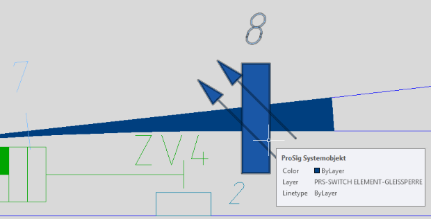
Illus.: Representation of a Derailer in the drawing
2.After inserting, the function Edit Object(s) is used to check the attributes of a derailer in the drawing.
Command Line: OE
Ribbon: ProSig EPU -> Tools -> Edit Object(s)
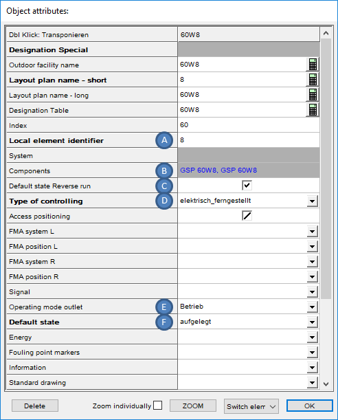
Illus.: Attributes of a Switch Element of a Double Derailer
oThe following attributes are relevant for the Switch element:
▪In the Attribute 'Local element identifier' (A), enter the name of the derailer.
▪The Attribute 'Components' (B) contains links to the associated switch component(s) of the derailer. The addition 'GSP' in the name of the switch components indicates that they are switch components of a derailer.
▪The Attribute 'Default state Reverse run' (C) is used for the derailer to specify that the element should automatically return to its default state once it is not occupied by a track route. The attribute 'Default state' (F) should also be specified.
▪For the Attribute 'Type of controlling' (D), the type of element to be placed needs to be specified.
▪The Attribute 'Operating mode outlet' (E) is used to define the element next to the normal operation (Element is movable) in a defined position.
▪The Attribute 'Default state' (F) can be filled with 'aufgelegt' or 'abgelegt' for derailers.
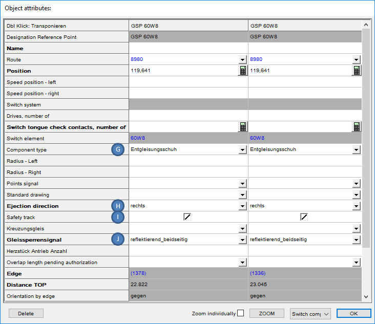
Illus.: Attributes of the Switch Components of a Double Derailer
oThe following attributes are relevant for the Switch components:
▪The Attribute 'Component type' (G) is automatically filled with the value 'Entgleisungsschuh' when the derailer is inserted.
▪The Attribute 'Ejection direction' (H) indicates the derailment direction of the vehicle crossing the derailer.
▪The Attribute 'Safety track' (I) is used to specify whether a safety track is provided for the derailer.
▪The Attribute 'Gleissperrensignal' (J) is used to specify the derailer indicator, if this is provided for the derailer. In the drawing, the representation of the derailer is updated corresponding to the setting of the attribute.
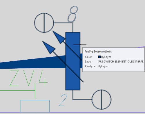
Illus.: Representation of a double derailer with derailer indicator reflective on both sides