Automatic Calculation of Correction Points

Contents
Process:
•Automatic calculation of Correction points
•Deleting Correction points
•Exporting Correction points
Requirements:
•Deriving the ETCS Overview Plan
Description:
The ProSig system provides a function for the automatic calculation of correction points in the ETCS overview plan. The correction points serve to mark deviations between the topological edge and the Chainage axis at data points, using signal data as reference. The determination of the determined deviations depends on the settings in the project attribute 'Baseline' (see Setting Up Planning Project) and in the object attribute 'TYPE' of a data point (see Inserting ETCS Track Equipment (Data Points)).
Distances |
Max. Distance error [m] |
Note |
|---|---|---|
Transponder group Type 23 |
2 |
|
Transponder group Type 24 |
2 |
|
Transponder to signal |
5 (SRS 2.3.0d) |
20 m (Baseline 3) |
Transponder to switch |
5 (SRS 2.3.0d) |
20 m (Baseline 3) |
Table: Criteria for calculating the Correction points
Procedure:
1.Start the function 'Ranges Editor'.
Command line: PRS_BAENDER
Ribbon: ProSig EPU -> Equipment ETCS -> Ranges Editor
2.Select the tab 'Correction Points'.
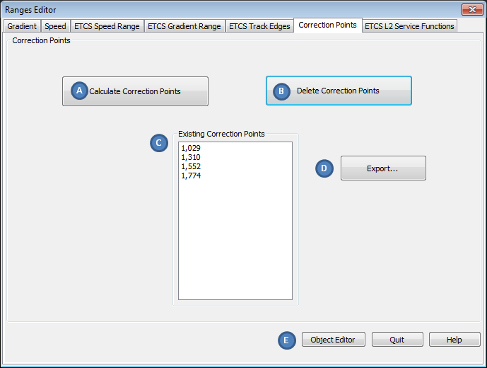
Illus.: Ranges Editor - Tab Correction Points
3.Click the button 'Calculate Correction Points' (A) to initiate automatic calculation of correction points.
oAfter the creation, the correction points are stored in the List 'Existing Correction Points' (C) with their designation. In the drawing they are displayed as a cross at the topological edge including their object attributes 'Location' and 'Correction Length'.
oThe Correction points are PSO's, and are stored as Point objects in the drawing on the Layer PRS-CORRECTION POINT.
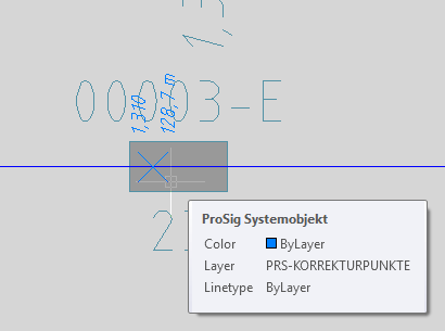
Illus.: Correction points on a Balise in the drawing
4.By clicking the button 'Delete Correction Points' (B), the existing correction points are deleted. The List 'Existing Correction Points' (C) is cleared and the correction points are removed from the drawing.
5.By clicking the button 'Export' (D), the correction points are exported from the drawing, see List of Correction Points.
6.After marking a correction point in the List (C), it is possible to display the object attributes with the button 'Object Editor' (E).
 |
 |
|---|---|
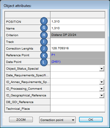
Illus.: Object attributes of a Correction point for a Data point Type 23 with reference point Signal |
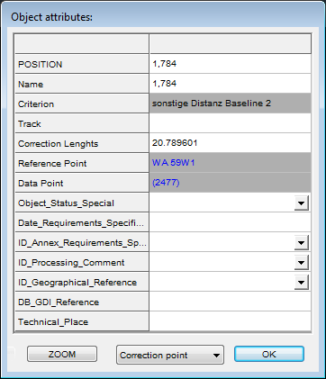
Illus.: Object attributes of a Correction point for Data point with reference point Switch, in a project with the project attribute Baseline 2 |
oThe Attribute 'POSITION' (F) is visible in the drawing, contains the location data of the correction point with respect to the Chainage axis. The value corresponds to the column 'Line-km' in the List of Correction Points.
oThe Attribute 'Name' (G) displays the correction point in the List 'Existing Correction Points' (C).
oThe value of the attribute 'Criterion' (H) describes the specification used in creating the correction point. The value corresponds to the column 'Criterion' in the List of Correction Points.
oThe value of the attribute 'Track' (I) contains the name of the track. The value corresponds to the column 'Track' in the List of Correction Points.
oThe Attribute 'Correction Length' (J) is visible in the drawing. The value contains the length of the determined incorrect distance between reference point and data point in meters, which is calculated depending on the respective criterion. The value corresponds to the column column 'Error-Track-KM' in the List of Correction Points.
oThe value of the attribute 'Reference Point' (K) refers to the reference point object (e.g. Signal, Switch). The designation of the reference point corresponds to the column 'Destination' in the List of Correction Points.
oThe value of the attribute 'Data Point' (L) refers to the Object Data point (Balise).