Inserting ETCS Track Equipment (Data Points)

Contents
Prozess:
•Einfügen von Datenpunkten für die Balisenplanung
Voraussetzung:
•Planen der Ausrüstung (insbesondere Signale - EPU)
Beschreibung:
Der Datenpunkt ist in ProSig ein punktförmiges Objekt, das an der topologischen Kante verortet ist. Je nach Einstellung der Eigenschaft 'DP-Typ' wird das Objekt in der Zeichnung dargestellt.
Ergänzende Beschreibungen zur Befüllung der Eigenschaften der Datenpunkte sind den folgenden Seiten zu entnehmen:
•Festlegen von Datenpunkt-Typen
•Erstellen und Zuweisen von Balisen
•Festlegen von Datenpunkt-Telegrammen
Informationen zur Formulierung des Objektes im PlanPro-Modell sowie eine allgemeine Beschreibung der Funktion 'Datenpunkte' sind auf der Seite Erstellen und Editieren von Datenpunkten zu finden.
Unterstützende Filmsequenz:
Einfuegen_der_ETCS_Streckenausruestung.mp4 (Größe 5,1 MB)
Vorgehensweise:
1.Die Funktion 'Datenpunkte' ausführen.
Befehlszeile: PRS_DATENPUNKT
Multifunktionsleiste: ProSig EPU -> Ausrüstung ETCS -> Datenpunkte
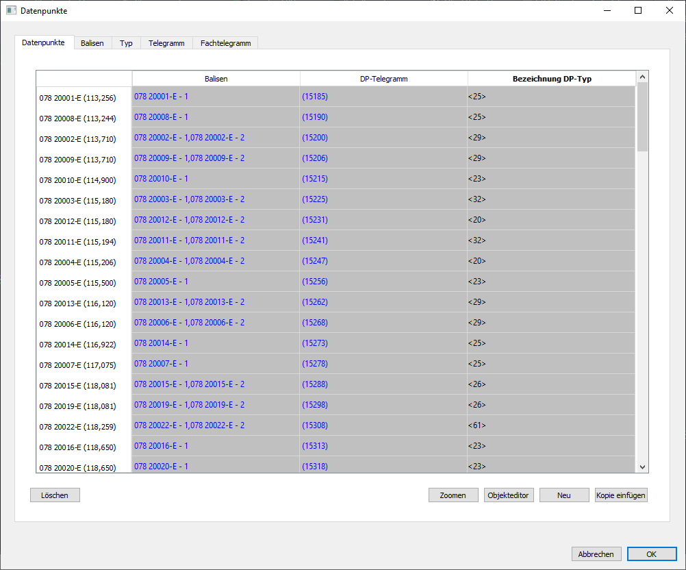
Bild: Kartenreiter 'Datenpunkte' im Dialog 'Datenpunkte'
2.Mit der Schaltfläche 'Neu' kann ein neues Objekt 'Datenpunkt' in die Zeichnung eingefügt werden.
oBeim Einfügen ist entweder ein Punkt auf der topologischen Kante (Layer PRS-TOPOLOGISCHE KANTE) oder ein Objekt als Bezugspunkt zu wählen. Der Datenpunkt kann beim Einfügen nachträglich verschoben werden, um diesen in einem definierten Abstand zum Bezugspunkt zu platzieren, siehe auch Punktförmige PSO - Einfügen an der topologischen Kante.
oDer Datenpunkt ist ein PSO und wird als punktförmiges Objekt je nach vorhandenem Datenpunkttyp auf dem Layer 'PRS-DATENPUNKT-GESTEUERT' oder 'PRS-DATENPUNKT-UNGESTEUERT' abgelegt.
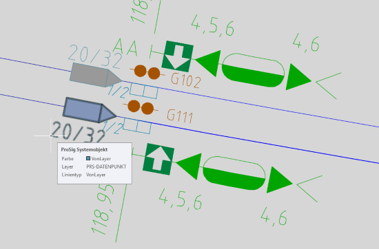
Bild: Darstellung eines Datenpunktes in der Zeichnung
3.Nach dem Einfügen des Datenpunktes sind über die Schaltfläche 'Objekteditor' alle relevanten Daten einzugeben.
 |
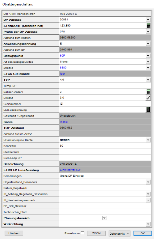 |
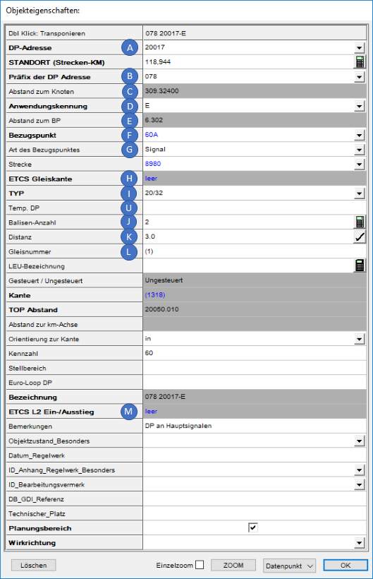
Bild: Eigenschaften eines Datenpunktes vom Typ <20,32> |
Bild: Eigenschaften eines Datenpunktes vom Typ <4,60> mit automatisch erzeugtem ETCS L2 Einstieg |
oIn die Eigenschaft 'Anwendungssystem' (A) ist das auf dem Balisenschild angegebene Hauptanwendungssystem einzutragen.
oDie Eigenschaft 'Ausrichtung' (B) gibt die physikalische Ausrichtung der Balisengruppe in Bezug auf die Topologierichtung an. Der Wert der Eigenschaft kann über die zugehörige Schaltfläche automatisch ermittelt werden, wenn dem Datenpunkt Balisen zugeordnet sind. Ist dem Datenpunkt eine Einzelbalise zugeordnet, wird hierbei automatisch der Wert 'keine' eingetragen.
oÜber die Eigenschaft 'Beschreibung' (C) kann eine ergänzende Beschreibung des Datenpunkts angegeben werden, z. B. bei Abweichungen bei Einmesspunkten.
oDer Wert der Eigenschaft 'Distanz' (D) bestimmt den Abstand der Balisen zueinander in einer Balisengruppe. Der Wert wird für die Datenpunkttabelle ETCS bei der Angabe zur relativen Lage der 2. Balise verwendet.
oÜber die Eigenschaft 'Sonstige Standortangabe' (E) kann eine Angabe zum Balisenstandort eingetragen werden. Beispiele hierfür sind '60W32L', 'BGRU 023' (= Berlin-Grunewald Nr. 23).
oÜber die Eigenschaft 'DP-Adresse' (F) kann dem Datenpunkt eine NID Adresse aus dem Vorrat zugewiesen werden.
oDie Eigenschaft 'Bezeichnung (G)' enthält die vollständige Bezeichnung des Datenpunktes (NID_C und NID_BG) ergänzt um die Anwendungskennung des Datenpunktes, für ETCS L2 z. B. der Wert 'E'. Der Wert kann für die Darstellung in der Zeichnung manuell überschrieben werden.
oDie Eigenschaft 'Kurzbezeichnung (H)' enthält die Bezeichnung des Datenpunktes ohne den Präfix NID_C.
oMit der Eigenschaft 'Temp. DP' (I) kann eine temporäre, benutzerdefinierte Bezeichnung des Datenpunktes angegeben werden, wenn zu Planungsbeginn noch keine Datenpunktadressen vorliegen. Wird nach dem Importieren der Datenpunktadressen die Eigenschaft 'DP-Adresse' belegt, wird automatisch die korrekte NID_BG in der Bezeichnung im sicherungstechnischen Lageplan verwendet.
oDie Eigenschaft 'DP-Typ' (J) enthält einen Verweis auf den DP-Typ des Datenpunktes, siehe hierzu auch Festlegen von Datenpunkt-Typen. Die Eigenschaft entspricht der Spalte 4 der Datenpunkttabelle. Die Beschreibung der Datenpunkttypen ist der Ril 819.1344 (Seite 70 bis 72) zu entnehmen.
oDie Eigenschaft 'Bezeichnung DP-Typ' (K) enthält den Wert der Eigenschaft 'DP-Typ' (J) und kann für die Darstellung in der Zeichnung manuell überschrieben werden.
oFür die Eigenschaft 'RBC' (L) sind die Radio Block Centres anzugeben, denen der Datenpunkt bekannt ist.
▪Zum Erstellen eines neuen RBC und anschließender Zuordnung siehe auch Editieren und Darstellen komplexer Daten - Zuordnen neu erzeugter Objekte.
▪Zum Zuordnen eines oder mehrerer bereits vorhandener RBC siehe auch Editieren und Darstellen komplexer Daten - Zuordnen von Objekten mittels Dialog. Die RBC sind hierbei zuvor bereits zu erstellen, siehe auch Erstellen des Radio Block Centres.
oDie Eigenschaft 'DP-Telegramm' (M) enthält Verweise auf ein oder mehrere DP-Telegramme. Zum Erstellen und Zuordnen eines DP-Telegramms siehe auch Festlegen von Datenpunkt-Telegrammen.
oDie Eigenschaft 'Balisen' (N) enthält Verweise auf eine oder mehrere Balisen. Zum Erstellen und Zuordnen einer Balise siehe auch Erstellen und Zuweisen von Balisen. Sind dem Datenpunkt mehr als eine Balise zugeordnet, wird die Eigenschaft 'Distanz' (D) für das Anwendungssystem 'L2' (A) automatisch mit dem Wert 3.0 Meter befüllt.
oKennzeichnet der Typ des Datenpunktes (J) einen ETCS L2 Ein- oder Ausstieg, wird als Wert der Eigenschaft 'ETCS L2 Ein-/Ausstieg (O) entsprechend ein Objekt Einstieg oder Ausstieg automatisch verlinkt. Zum Bearbeiten der Eigenschaften des verlinkten Objektes weiter bei Schritt 4.
4.Wird einem Datenpunkt ein Datenpunkttyp zugeordnet, für den ein ETCS L2 Ein-/Ausstieg gemäß Ril 819.1344 erforderlich ist, wird das Objekt 'ZUB Bereichsgrenze' automatisch erzeugt und in der Eigenschaft 'ETCS L2 Ein-/Ausstieg' (O) zugeordnet. Dieses wird z. B. für die Datenpunkttypen 4 (Einstiegs-Grenzdatenpunkt) und 60 (Grenzdatenpunkt für reguläre Ausstiege) vorgenommen.
oZum manuellen Erstellen einer 'ZUB Bereichsgrenze' als ETCS L2 Ein-/Ausstieg für einen Datenpunkt mit einem anderen Datenpunkttypen siehe auch Editieren und Darstellen komplexer Daten - Zuordnen neu erzeugter Objekte.
oZum Ändern der Zuordnung zu einem ETCS L2 Ein- oder Ausstieg siehe auch Editieren und Darstellen komplexer Daten - Zuordnen von Objekten mittels Dialog. Beim Entfernen eines Ein- oder Ausstieges über den Dialog, bleibt das Objekt im Projekt weiterhin erhalten. Es wird nur der Verweis auf das Objekt in der Eigenschaft 'ETCS L2 Ein-/Ausstieg' (O) entfernt.
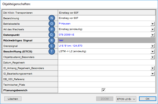
oDurch Doppelklick auf den Wert der Eigenschaft 'ETCS L2 Ein-/Ausstieg' (O) werden die Objekteigenschaften des zugehörigen Ein- oder Ausstieges angezeigt und können bearbeitet werden. Zur Befüllung der Eigenschaften für eine ZUB Bereichsgrenze als Ein- oder Ausstieg siehe auch Definieren der ZUB Bereichsgrenzen, Schritt 3.
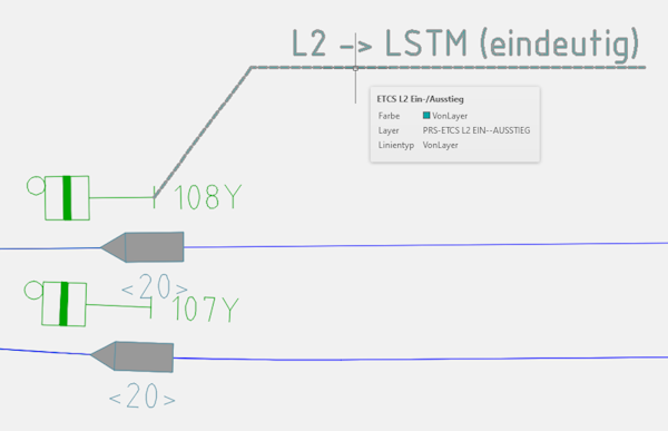
oNach dem Befüllen der Eigenschaften für einen Ein- oder Ausstieg wird die ZUB Bereichsgrenze entsprechend in der Zeichnung dargestellt.

Bild: Darstellung einer ZUB Bereichsgrenze als Einstieg nach L2 mit Baseline 2 in der Zeichnung
oIn bestehenden Projekten können auch noch die Objekte 'ETCS L2 Ein-/Ausstieg' vorkommen. Die Eigenschaften und die Darstellung der Objekte in der Zeichnung wird nachfolgend beschrieben. Auch diese Objekte werden beim Export in die Tabelle der ETCS L2 Ein-/Ausstiege weiterhin unterstützt.
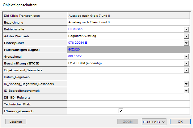
Eigenschaften und Darstellung eines Objektes 'ETCS L2 Ein-/Ausstieg' in bestehenden Projekten
oDer Wert der Eigenschaft 'Bezeichnung' (P) entspricht der Spalte D 'Bezeichnung Ein-/Ausstieg' der Tabelle ETCS Level 2 Ein-/Ausstiege. oDer Wert der Eigenschaft 'Betriebsstelle' (Q) entspricht der Spalte C 'Betriebsstelle' der Tabelle ETCS Level 2 Ein-/Ausstiege. Die Belegung des Wertes wird zurzeit noch nicht unterstützt. Der Wert kann nach dem Export in die Exceltabelle eingetragen werden. oDer Wert der Eigenschaft 'Art des Wechsels' (R) entspricht der Spalte E 'L2 Ein-/Ausstieg' der Tabelle ETCS Level 2 Ein-/Ausstiege und ist entsprechend der Ril 819.1344 aus der Liste auszuwählen. oDer Wert der Eigenschaft 'Datenpunkt' (S) enthält einen Link auf den zugehörigen Datenpunkt. Wurde für die Eigenschaft 'Grenzsignal' keine Auswahl getroffen, wird für die Spalte G 'Grenzsignal / Einstiegs-Grenz-DP' der Tabelle ETCS Level 2 Ein-/Ausstiege die DP-Adresse (K) des zugehörigen Datenpunktes automatisch eingetragen. oDie Eigenschaft 'Rückwärtiges Signal' (T) wird beim Erzeugen des ETCS L2 Ein-/Ausstiegs automatisch belegt, sofern ein rückwärtiges Signal ermittelt werden kann. oDer Wert der Eigenschaft 'Grenzsignal' (U) ist zu belegen, wenn zu diesem Ein- bzw. Ausstieg in der Spalte G 'Grenzsignal / Einstiegs-Grenz-DP' der Tabelle ETCS Level 2 Ein-/Ausstiege ein Signal anzugeben ist. Über den Kontextmenüpunkt Objekt(e) zuordnen mittels Dialog können der Eigenschaft ein oder mehrere Signale oder Datenpunkte zugeordnet werden. oDer Wert der Eigenschaft 'Beschriftung (ETCS)' (V) kann entsprechend der Ril. 819.1344 aus der Liste ausgewählt werden. Die Beschriftung des Ein- oder Ausstiegs wird anschließend auf dem Layer PRS-ETCS L2 EIN--AUSSTIEG abgelegt. ▪Wurde ein 'Grenzsignal' (U) eingetragen, wird die 'Beschriftung (ETCS)' (V) am Grenzsignal dargestellt. ▪Wurde kein 'Grenzsignal' (U) eingetragen, wird die 'Beschriftung (ETCS)' (V) stattdessen am 'Datenpunkt' (S) dargestellt. ▪Wurden weder 'Grenzsignal' (U) noch 'Datenpunkt (S) eingetragen, erfolgt keine Darstellung der Beschriftung. |