Defining the Defaults

Contents
Process:
•Define the specifications that result from the Project requirements.
Requirements:
•Setting Up the Cable Overview Plan
Description:
Before starting the cable planning, the basic settings for creating the cable overview plan should be defined. This determines which type of interlocking is used and which cable catalogue to be used. The standard specifications of excess lengths and cable core reserve for tail and line cables should be checked and if necessary, they should be adapted to the project specifications. The values are saved after the first setting and restored after reloading the drawing .
Procedure:
1.Start the function 'Main Module' to create the Cable overview plan.
Command Line: KUP_HPT
Ribbon: ProSig EPU -> Wiring -> Cable Overview Plan -> Main Module
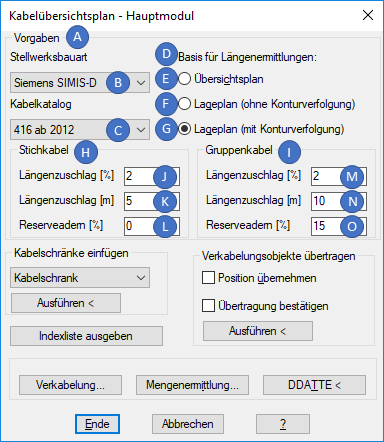
Illus.: Dialog Cable overview plan - Main module
1.Im Bereich 'Vorgaben' (A) können die Grundeinstellungen zum Erstellen des Kabelübersichtsplans festgelegt werden. Die Einstellungen werden in der Zeichnung gespeichert und nach erneutem Laden der Zeichnung wieder hergestellt.
oÜber das Dropdown für die Stellwerksbauart (B) ist der für die Verkabelung zugrundeliegende Stellwerkstyp auszuwählen. Der Stellwerkstyp hat Auswirkung auf den Aderbedarf der zu verkabelnden Objekte und die Maximalwerte der elektrischen Parameter der Kabelverbindungen.
oÜber das Dropdown für den Kabelkatalog (C) ist der zu verwendende Kabelkatalog auszuwählen. Dieser legt die zur Verfügung stehenden Kabel fest, die für die Verkabelung verwendet werden.
3.Über den Bereich 'Basis für Längenermittlungen' (D) ist die Art der Ermittlung für die Kabellängen festzulegen. Die Einstellungen werden in der Zeichnung gespeichert und nach erneutem Laden der Zeichnung wieder hergestellt.
oFür die Option 'Übersichtsplan' werden bei der Übertragung zu verkabelnder Objekte und bei der Einfügung von Kabelschränken Standorteigenschaften in die jeweiligen Objekte im Kabelübersichtsplan eingetragen. Nach dem Einfügen solcher Objekte ist ein nachträglicher Wechsel der Basis zwischen 'Lageplan' und 'Übersichtsplan' nicht möglich.
Der Wechsel zwischen 'Lageplan (ohne Konturverfolgung)' und 'Lageplan (mit Konturverfolgung)' kann jederzeit erfolgen.
oDie Option 'Übersichtsplan' (E) kann ausgewählt werden, wenn es sich bei dem Plan, der für die Ermittlung der Kabellängen verwendet wird, um einen sicherungstechnischen Übersichtsplan handelt. Die Längenermittlung erfolgt hierbei automatisch ohne Benutzereingaben.
▪Die Berechnung der Gruppenkabellänge erfolgt automatisch aus der Differenz der X-Koordinaten der WKS-Standorte der anschließenden Kabelschränke, Verteiler etc.
▪Die Berechnung der Stichkabellänge erfolgt automatisch aus den Differenzen der X-Koordinaten der WKS-Standorte des zu verkabelnden Objektes und des anschließenden Kabelschrankes, Verteilers etc.
▪Es ist darauf zu achten, dass die Ausrichtung (durchgehende Hauptgleise) des zugrundeliegenden Übersichtsplans parallel zur X-Achse des WKS liegt.
▪Die Kabelschränke sind an der WKS-X-Koordinate einzufügen, die ihrer WKS-Position im Übersichtsplan entspricht. Die WKS-X-Koordinate des Einfügepunktes wird automatisch als Attribut im Kabelschrank gespeichert. Im Anschluss können die Kabelschränke beliebig verschoben werden.
▪Kabellängen in Y-Richtung (z.B. bei Querungen) werden ignoriert, so dass nur überschlägige Größen zur Verfügung stehen.
oDie Option 'Lageplan (ohne Konturverfolgung)' (F) kann ausgewählt werden, wenn es sich bei dem Plan, der für die Ermittlung der Kabellängen verwendet wird, um einen Lageplan handelt. In diesem Fall kann die Länge von Kabeln durch die Wahl von Elementen bestimmt werden, die den Kabelweg beschreiben. Dabei gibt es grundsätzlich drei Möglichkeiten, die Länge eines Kabels zu ermitteln: Wahl eines vorhandenen Kabels, Kabelverlauf über den Lageplan bestimmen oder Leereingabe.
Wahl eines vorhandenen Kabels:
▪Bei Auswahl eines vorhandenen Kabels im Kabelübersichtsplan werden die Länge und die Einträge für die Längenzuschläge aus diesem Kabel in die Eigenschaften des neu erzeugten Kabels übernommen.
Kabelverlauf über den Lageplan bestimmen:
▪Die Längen von Linien, Bögen, Polylinien, ProSig-Kabelkanälen, ProSig-Rohrtrassen und ProSig-Erdkabeltrassen werden direkt aus den Längen der gewählten Objekte übernommen. Die Wahl von Blöcken (z.B. Schächten) ist ebenfalls möglich, sofern ihnen in der Bauteildatei MMLAENGE eine Länge zugeordnet ist.
▪Besteht ein Kabelkanal aus mehreren Linien, wird die Länge nur einmal berücksichtigt, auch wenn alle Linien markiert wurden.
▪Nicht zulässige Elemente werden automatisch aus dem Auswahlsatz herausgefiltert.
▪Bei der Bestimmung des Kabelwegs wird keine Vollständigkeitskontrolle durchgeführt. Wurden Elemente, die eigentlich den Kabelweg beschreiben, nicht in die Auswahl aufgenommen, werden sie auch nicht in die Längenberechnung für die Kabel mit einbezogen.
Leereingabe:
▪Wurde die Anfrage zur Ermittlung der Kabellänge mit einer Leereingabe (<ENTER>) beantwortet, kann anschließend eine explizite Länge als Zahl eingegeben werden.
oDie Option 'Lageplan (mit Konturverfolgung)' (G) kann ausgewählt werden, wenn es sich bei dem Plan, der für die Ermittlung der Kabellängen verwendet wird, um einen Lageplan handelt. Dabei gibt grundsätzlich drei Möglichkeiten, die Länge eines Kabels zu ermitteln: Wahl eines vorhandenen Kabels, Kabelverlauf über den Lageplan bestimmen oder Leereingabe.
Wahl eines vorhandenen Kabels:
▪Bei Auswahl eines vorhandenen Kabels im Kabelübersichtsplan werden die Länge und die Einträge für die Längenzuschläge aus diesem Kabel in die Eigenschaften des neu erzeugten Kabels übernommen.
Kabelverlauf über den Lageplan bestimmen:
▪Hierbei erfolgt die Längenermittlung der Kabel durch Angabe des Start- und des Zielpunktes des Kabelwegs. Anschließend kann anhand der Konturverfolgung der Kabelverlauf festgelegt und somit die Länge ermittelt werden.
▪Die gemessenen Längen werden standardmäßig mit Zuschlägen versehen.
Leereingabe:
▪Wurde die Anfrage zur Ermittlung der Kabellänge mit einer Leereingabe (<ENTER>) beantwortet, kann anschließend eine explizite Länge als Zahl eingegeben werden.
4.In den Bereichen 'Stichkabel' (H) und 'Gruppenkabel' (I) können prozentuale (J, M) und absolute (K, N) Zuschläge für Kabellängen und Reserveadern (L, O) jeweils getrennt für Stich- und Gruppenkabel festgelegt werden. Diese werden bei der Kabellängenermittlung und der Auswahl der Kabel automatisch berücksichtigt.
▪Die tatsächliche Kabellänge ergibt sich aus: Gemessene Länge * prozentualer Zuschlag + absoluter Zuschlag.