Setting Up the Cable Overview Plan

Contents
Process:
•Setting up the Cable overview plan in the Cable layout plan.
Requirements:
Description:
No separate plan type is available for the Cable overview plan. There are existing references between the Cable layout plan and the Cable overview plan, hence a permanent interface is required. The Cable layout plan and Cable overview plan are displayed in a common drawing area during cable planning, whereby the Cable overview plan is displayed in a second view port adjacent to or below the Cable layout plan. It is mandatory that both view ports use a common UCS. For the positioning of the cable cabinets, the MSTT and the CBI it is recommended to create a grid of auxiliary lines in the Cable overview plan.
Procedure:
1.To display the Cable overview plan, it is recommended to draw a grid of auxiliary lines below the Cable layout plan.
oA distance of 40 drawing units between the auxiliary lines has proved to be feasible.
oFor a better overview, the auxiliary lines for positioning the cable cabinets should be plotted slightly longer.
oTo the left and right of the cable cabinet, shorter auxiliary lines should be drawn for positioning the transferred objects.
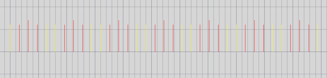
Illus.: Grid of auxiliary lines for easier positioning of Objects in the Cable overview plan
2.Since the Cable layout plan and Cable overview plan are placed in the same drawing area, splitting the view ports makes the editing more convenient. By splitting the screen into two view port, the active view port changes automatically when you perform certain functions.
oAuto CAD's view port configuration can be used to create a second view port for the Cable overview plan.
oThe User Coordinate System (UCS) should not be changed after creating the second view port.
oThe view ports are identified by selecting an object in the respective view port during the first automatic change, see also Inserting Cable Cabinets in the Cable Overview Plan, Insert Cable Cabinet.
3.The following System Variables should be set in the view port of the Cable overview plan:
oThe Object snap (OSNAP) should be issued.
oSwitch on the drawing grid (GRIDMODE = 1).
oThe Snap should be switched on (SNAPMODE = 1).
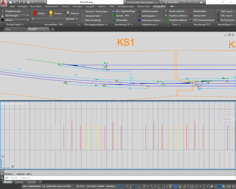
Illus.: Configured view-ports as a preparation for Cable planning