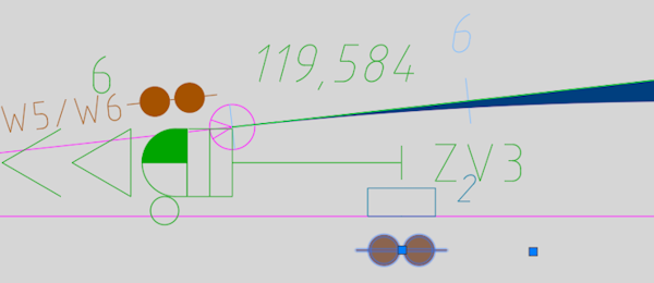
ProSig System Objects
Many EPU functions are complex and systematically demanding. Very often, the attributes of the created and edited SCT-objects will change their representation (CAD representatives) in the plans. In order to meet this increased systematic demand, the ProSig 7 EPU introduced the so-called ProSig System Objects (PSO for short), in which intelligent and interactive planning support is partly only possible in some cases. The basic technology behind the PSO are the AutoCAD Custom Objects, which have been designed accordingly for the EPU functions.
The following points must be observed when editing the PSO:
For Dot-like PSO, that are assigned to one or more topological edges, during insertion a point must be selected on these edges. Example: A Fictitious Signal is inserted at the topological edge. If a dot-like PSO has to be inserted that receives a station at the topological edge (layer PRS-TOPOLOGICAL EDGE), proceed as follows:
1.Start the procedure for inserting the dot-like PSO (e.g. PRS_EPU_EINF). The functionalities for inserting the objects are described in the associated processes.
2.The prompt in the command line 'Select insertion point or point object:' offers the following possibilities:
Table: Possibilities for selecting the insertion point for the dot-like PSO, which is located at the topological edge
3.When prompted in the command line 'Specify lateral position and working direction:', select a point in one of the displayed quadrants. The selection determines the position of the object to be inserted.
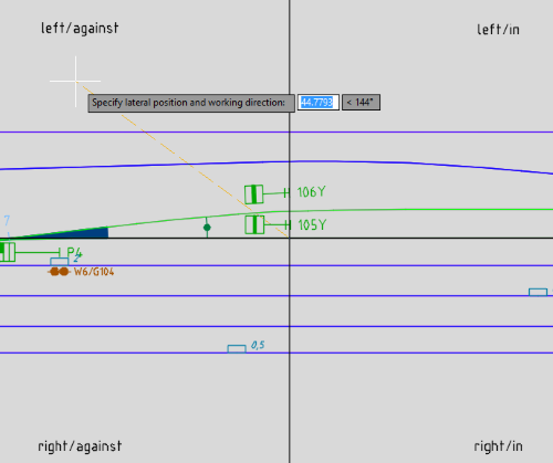 Illus.: Determination of the position and working direction of a dot-like, located PSO during insertion
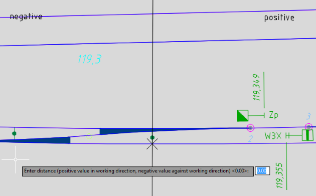
4.When the prompt 'Move object along topology (Yes/No)' is displayed with o'N' if the object is created at the insertion point. o'Y' if the object is moved from the marked point along the topological edge. ▪At the location point of the object, a temporary vertical line is drawn perpendicular to the topological edge with the information positive and negative. At the same time the prompt 'Enter distance (positive value in working direction, negative value against working direction) <0.00>:' is displayed. ▪The information depends on the working direction of the object to be inserted: in the working direction of the object the information is positive, against the working direction of the object negative. ▪If the object was inserted in point 3 without a special working direction (i.e. direction = both), the object is moved in the direction of the planning direction if a positive value is specified. If a negative value is specified, the object is shifted in the opposite direction to the planning direction. ▪After entering the distance and then confirming with the Enter key, the displacement is carried out accordingly. If necessary, the object can then be moved again from the newly determined insertion point.
▪If the function finds several target points due to several possible mobile paths, all target points are temporarily marked on the topology. The prompt 'Multiple target positions found. Target positions marked. Select target position:'. After specifying the target position, the object can be moved again from the newly determined insertion point if required.
5.The object is automatically located during insertion. |
For Dot-like PSO,that have no relation to the track edge, a point in the free drawing area must be selected.
If you want to insert a dot-like PSO in the free drawing area, proceed as follows:
1.Start the process for inserting the dot-like PSO (e.g. PRS_EPU_EINF). The functionalities for inserting the objects are described in the associated processes.
2.In the prompt 'Specify insertion point:' a point must be selected in the drawing area. The position of the selected point is described in the corresponding process.
3.The prompt 'Specify angle for insertion:' draws a line from the insertion point to the crosshairs of the mouse pointer. By selecting another point in the drawing, the angle is calculated. The angle determines the positioning of the visible attributes of the object.
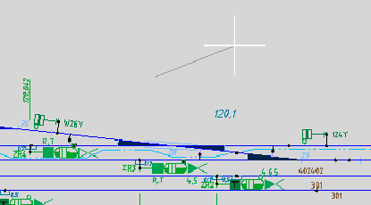 Illus.: Determination of the insertion angle of the non-located, dot-like PSO |
When inserting PSO Area objects,the corresponding topological edges (layer PRS-TOPOLOGICAL EDGE) or the border points on the topological edge are selected depending on the object type.
When creating an area object, the following options are available for selection:
Table: Overview of Possibilities for Creating Area Objects In some cases, a specific object is required for the area object at the selected boundary point. If the object does not exist, the corresponding insertion process is started automatically. Example: Inserting a Track clearance section element. If it does not exist, FMA components are created at the border points. |
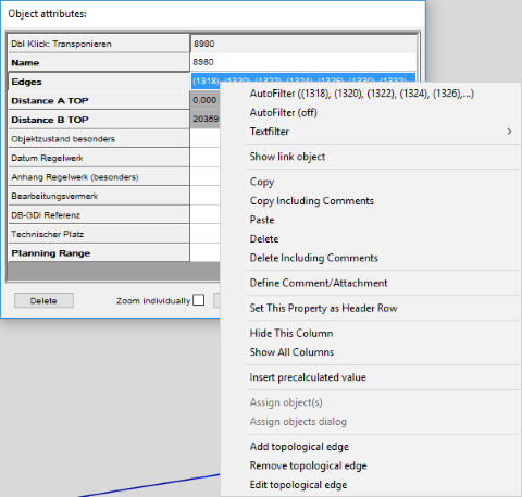
With a PSO Area object the assigned topological edges can be edited afterwards. This can be done by activating the context menu in the corresponding object attributes.
Table: Overview of the Options for Editing Area Objects |
To move PSO or to move / rotate its sub-objects, you must set the AutoCAD system variables GRIPS = 1 or 2 and PICKFIRST = 1.
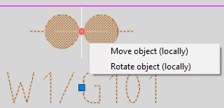
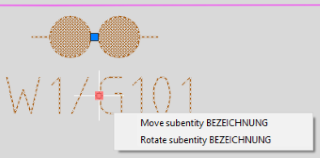
After selecting a ProSig system object, a grip in the form of a blue square is displayed for the PSO and its sub-objects. After selecting an individual grip, it is highlighted in red and a selection menu is displayed. The functionality was adapted to the behavior of AutoCAD, so that you can switch between the selection options of the menu via CTRL.
Depending on the PSO and the marked grip, different Move/Rotate options are available:
•PSO Area Object itself cannot be moved / rotated, but only its sub-objects. This applies, for example: to the objects Track Identifier, Track clearance section or Overlap. •For Dot-like PSO,different entries are available in the selection menu depending on the plan type and grip selected.
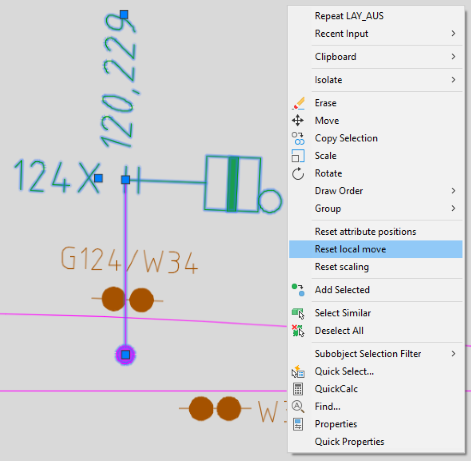
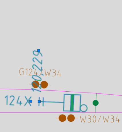
Table: Selection options for moving/rotating dot-like PSO according to plan type •If a dot-like object is moved locally, a local vector for the object type is displayed in the drawing (Layer PRS-<OBJECT TYPE>-LOKALVEKTOR), e.g. PRS-SIGNAL-LOKALVEKTOR. To reset the local move or attribute positions of a PSO, first mark it. The object context menu can then be activated by right-clicking. •By selecting the menu item 'Reset local move' the local move of the object is reversed. The local vector (Layer PRS-<OBJECT TYPE>-LOKALVEKTOR) created for the local displacement is then no longer displayed.
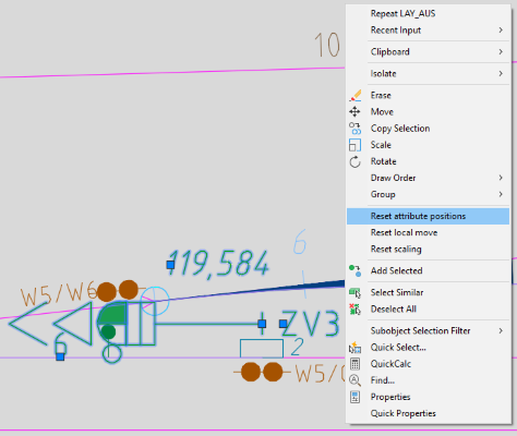
•By selecting the menu item 'Reset attribute positions' the sub-objects (e.g. name or position) are reset by shifting / rotating. The attributes receive their default position as after inserting the PSO.
|
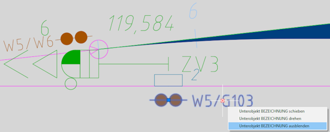
Voraussetzung zum Ausblenden von Unterobjekten eines PSO ist das Setzen der AutoCAD-Systemvariablen GRIPS = 1 oder 2 und PICKFIRST = 1.
Nach Auswahl eines ProSig Systemobjekts wird für das PSO und deren Unterobjekte jeweils ein Grip (Griff) in Form eines blauen Quadrats angezeigt. Nach Auswahl eines einzelnen Grips wird dieser rot markiert und ein Auswahlmenü eingeblendet. •Durch Auswahl des Menüeintrags 'Unterobjekt <ATTRIBUTNAME> ausblenden' wird das Unterobjekt (z. B. Bezeichnung einer FMA-Komponente) nur für das zugehörige Objekt in der Zeichnung ausgeschaltet. Für andere Objekte (hier z. B. FMA-Komponenten) bleibt das Unterobjekt sichtbar, wenn der Layer des Attributes eingeschaltet ist.
•Durch Auswahl des Menüeintrags 'Unterobjekt <ATTRIBUTNAME> einblenden' wird das Unterobjekt wieder sichtbar geschaltet.
•Wurden mehrere Unterobjekte eines PSOs ausgeblendet, können diese über den Menüeintrags 'Ausgeblendete Unterobjekte anzeigen' des Objektkontextmenüs gemeinsam wieder eingeschaltet werden. |
The scaling of dot-like PSO is carried out via the AutoCAD function 'SCALE' (VARIA). PSO area objects cannot be scaled. When scaling PSO, note that they can be reduced or enlarged by a maximum of 30%. Proceed as follows:
4.After executing the AutoCAD function 'Scale' (VARIA), one or more PSOs can be selected to be scaled. 5.Then specify the base point of a PSO to be scaled. 6.Enter a scaling factor between 0.7 and 1.3 and confirm with the Enter key.
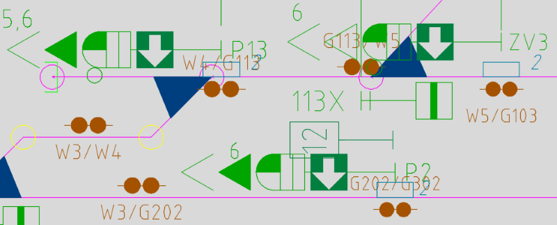 Illus.: Example of a section of an overview plan, signals and FMA components with scaling factor 1 (standard)
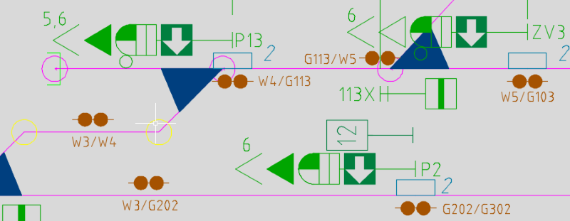 Illus.: Example Section of an overview plan, signals and FMA components with scaling factor 0.8 (i.e. reduced by 20%)
To reset the scaling of a PSO, first mark it. The object context menu can then be activated by right-clicking. A prerequisite is setting the AutoCAD system variable as PICKFIRST = 1 •By selecting the menu item 'Reset local move' the scaling of the PSO is undone, i.e. reset to the scaling factor 1. |
All PSOs are positioned on separate layers, assignment of which to the PSOs is controlled via the ProSig project. The system furthermore defines a separate attribute layer for every attribute of a PSO shown. The basis for naming these attribute layers is the master layer name of the PSO. Example: A point of gradient change is positioned on the layer PRS-GRADIENT CHANGE. The attributes of the point of gradient change are positioned on the two layers PRS-GRADIENT CHANGE-POSITION (attribute 'Position') and PRS-GRADIENT CHANGE-HEIGHT [M] (attribute 'Height [m]').
In ProSig, the following layers are defined for PSO's:
|

