Alignment of Schematic Plans

Contents
Prozess:
•Ableiten eines schematischen Übersichtsplans
Voraussetzung:
•Vorbereitungen im sicherungstechnischen Lageplan
Beschreibung:
Dem bestehenden Projekt wird eine leere Zeichnung zugeordnet. Die Zeichnungseinstellungen Planart und Maßstab sind dringend zu überprüfen, da sie nach dem Einbinden in das Projekt nicht mehr verändert werden können.
Nach dem Öffnen des Übersichtsplanes werden die ProSig Systemobjekte zunächst automatisch im Ursprung der Zeichnung positioniert.
Vorgehensweise:
1.Das Zuordnen der Zeichnung zu einem Planungsprojekt erfolgt über die Funktion 'Projektmanager'.
Befehlszeile: PRS_PROJEKTMANAGER
Multifunktionsleiste: ProSig EPU -> ProSig-Projekt-> Projektmanager
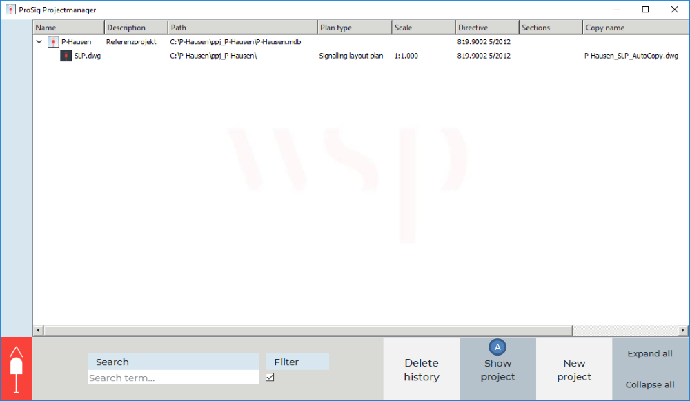
Bild: Der Projektmanager zeigt ein Projekt mit einem zugeordneten sicherungstechnischen Lageplan an
oWird das Projekt, dem die Zeichnung als schematischer Plan zugeordnet werden soll, nicht im Projektmanager angezeigt, ist es mit der Schaltfläche 'Projekt anzeigen' (A) zu öffnen.
2.Durch Rechtsklick auf das Projekt und Auswahl des Menüpunktes 'Neue Zeichnung' kann dem Projekt eine weitere AutoCAD-Zeichnung zugeordnet werden.
3.Im Anschluss können die Zeichnungseigenschaften der zugeordneten DWG festgelegt werden. Durch Doppelklick mit der linken Maustaste in das jeweilige Feld sind die Eigenschaften einzutragen.
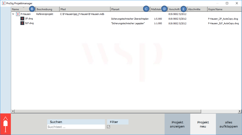
Bild: Festlegen der Eigenschaften für einen sicherungstechnischen Übersichtsplan
oDie Eigenschaft 'Name' (B) ist mit dem Namen der Zeichnung zu belegen. Wird kein Name eingetragen, wird der Name der Zeichnung beim Speichern automatisch je nach eingestellter Planart festgelegt, so dass für den Sicherungstechnischen Übersichtsplan der Name automatisch mit 'ÜP' belegt wird.
oDie Eigenschaften 'Planart' (C), 'Maßstab' (D) und 'Vorschrift' (E) sind für den Sicherungstechnischen Übersichtsplan über die Dropdown-Liste entsprechend festzulegen.
4.Anschließend die neu zugeordnete Zeichnung speichern durch Rechtsklick auf die Zeichnung und Auswahl des Menüpunktes 'Speichern'.
5.Durch Rechtsklick auf die neu zugeordnete Zeichnung und Auswahl des Menüpunktes 'Öffnen' die Zeichnung öffnen.
oProSig Systemobjekte werden automatisch in schematische Pläne abgeglichen, können aber aufgrund der fehlenden Topologie und Kilometrierung nicht korrekt positioniert werden. Erst nach dem Übertragen der Topologie und der Kilometrierung aus dem Lageplan werden die PSO entsprechend ihrer Kilometrierung entlang der Topologie positioniert.