Deriving Schematic Plans

Contents
Process:
•Entering the levels of the topological edges in the Signalling layout plan
•Derivation of a Schematic Overview Plan
•Transferring the chainage from the Signalling layout plan
•Creation of the topology and the track equipment in the Schematic Overview plan
Requirements:
Description:
After the creation of the Signalling layout plan, it is possible to create Schematic plans (especially the Schematic Overview Plan) in different scales from the ProSig project. For the correct representation of the topology, the levels of the topological edges have to be defined in the layout plan.
Subsequently, an empty drawing is assigned to the existing project. The drawing should be saved under the desired name. A blank drawing can only be assigned to an existing project, if no other drawing of this project is open.
When defining the drawing attributes Plan type and Scale, it is important to check the attributes, as they cannot be changed after integration into the project.
ProSig system objects are automatically aligned into Schematic Plans, but cannot be positioned due to the missing Chainage and Topology. The Topology can be generated, after the Chainage data are transferred to the Overview Plan. ProSig system objects are then automatically positioned along the topology.
To derive further schematic plans after the creation of the first overview plan, it is possible to generate fully automated plans from the existing overview plan.
The Following steps are processed in detail:
•Preparations in the Signalling Layout Plan
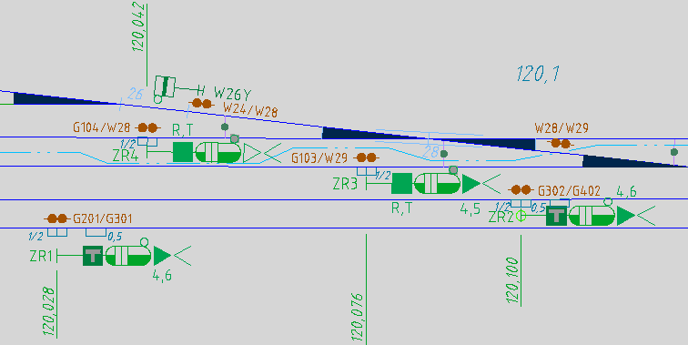
Illus.: Situation in the Signalling Layout Plan
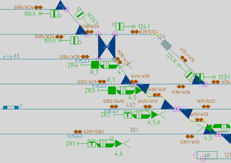
Illus.: The corresponding representation in the Schematic Plan