Preparations in the Signalling Layout Plan

Contents
Process:
•Determining the levels to the Topological Edges
•Verifying the registered routes and positions at the Topological nodes
Requirements:
Description:
After the Signalling layout plan has been created, it is possible to create Schematic plans (especially the Schematic overview plan) in different scales from the ProSig project.For the correct representation of the topology in the schematic plan, the following requirements for the alignment of the schematic plan have to be ensured in the layout plan:
•The Chainage axis of all routes are sufficiently long to give all topological nodes a location in relation to their respective route.
•The Route assignment of the topological edges is checked and unambiguous.
•The Locations and routes of the topological nodes are checked.
•The Levels are defined for all topological edges.
Procedure:
1.First, the levels of the topological edges are entered manually in the Signalling layout plan. The function Edit Object(s) is used to select the corresponding topological edges for each level in the drawing.
Command Line: OE
Ribbon: ProSig EPU -> Tools -> Edit Object(s)
oIf no levels are entered for topological edges, the topology cannot be aligned to the schematic plan.
oThe entry of the edge level is executed in construction stage 0.
oThe Edge levels are defined separately for each route.
oFor an easier handling, it is recommended to switch off all layers except the layers PRS-TOPOLOGICAL EDGE and PRS-TOPOLOGICAL NODE.
2.At first, a level of the topological edges has to be defined as level 0. For all topological edges of this level, for the attribute 'Level (Topology)' (A) the value '0.0' should be entered.
oThe Level 0 has to be set separately for each route. It is recommended to select the topological edges for Level 0 that lie on the Chainage axis or correspond most closely to the Chainage axis.
3.The Levels of the topological edges have to be defined starting from Level 0.
oThe levels of the topological edges, starting from level 0 in the direction of the ascending Chainage to the left of the Chainage axis of the line, should be specified as follows:
▪Main levels are specified in positive full increments (1.0, 2.0, 3.0, ...).
▪Intermediate levels are specified for topological edges that represent a connection between two topological edges. Intermediate levels are specified in positive half-intervals (0.5, 1.5, 2.5, ...).
oThe levels of the topological edges, starting from level 0 in the direction of the ascending Chainage to the right of the Chainage axis of the line, should be specified as follows:
▪Main levels are specified in negative full increments (-1.0, -2.0, -3.0, ...).
▪Intermediate levels are specified for topological edges that represent a connection between two topological edges. Intermediate levels are specified in negative half-intervals (-0.5, -1.5, -2.5, ...).
oIf the Chainage of the route is opposite to the Chainage of the planning direction, then the levels of the topological edges are specified starting from level 0 to the left of the Chainage axis of the route with negative values and to the right with positive values.
oExample for setting the Main and Intermediate levels of Topological edges:
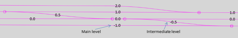
Illus.: Example for Setting the Level of Topological Edges
oExample for setting the levels for the Topological edges of a Double slip:
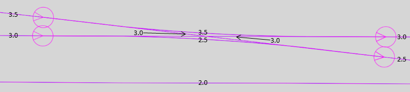
Illus.: Setting the Levels for the Topological Edges of a Double slip
4.The Step 2 and 3 should be repeated for each route.
5.With the function Edit Object Type, it is possible to check whether the attribute 'Level (Topology)' (A) is assigned to all topological edges by selecting the Object type 'Topological Edge'.
Command Line: PRS_OEA
Ribbon: ProSig EPU -> Tools -> Edit Object Type
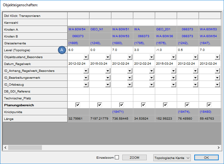
Illus.: Display the Object Attributes for the Object Type 'Topological Edge'
6.For the correct positioning of the topological nodes in the Signalling overview plan, it is necessary to check whether the attributes 'Route' and 'Position' for all topological nodes have been assigned automatically. Execute the function Edit Object Type and select the Object type 'Topological Node'.
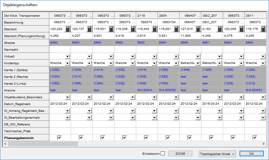
Illus.: Display of Object Attributes for the Object Type 'Topological Node'
oThe Attribute 'Route' is automatically filled with one or more assigned routes.
oThe Attribute 'Position' is automatically filled with one or more positions according to the assigned routes.
7.The Functions Check Topological Edges and Check Topological Nodes are used to verify that the line assignment of all topological edges are unique and that the topological nodes have Chainage information. Then save and close the Signalling layout plan.