Align Distance Indicators

Contents
Process:
•Aligning the distance indicators of overlaps and PZB element assignments
Requirements:
•Planning of Intermittent Train Control
Description:
With the function 'Align Distance Indicators' the distances of overlaps and PZB element assignments can be aligned in accordance with an angle from a reference point in the drawing.
Procedure:
1.Start function 'Align Distance Indicators'.
Command Line: PRS_PFEILDREH
Ribbon: ProSig EPU -> Tools -> Services -> Align Distance indicators
oAfter calling the function, the prompt 'D-Weg oder PZB-Element 'Abstandsangaben wählen' is displayed via the command line.
2.Select one or more distances to overlap or PZB elements in the drawing to be aligned. The object selection can be terminated by pressing the Enter key or the right mouse button.
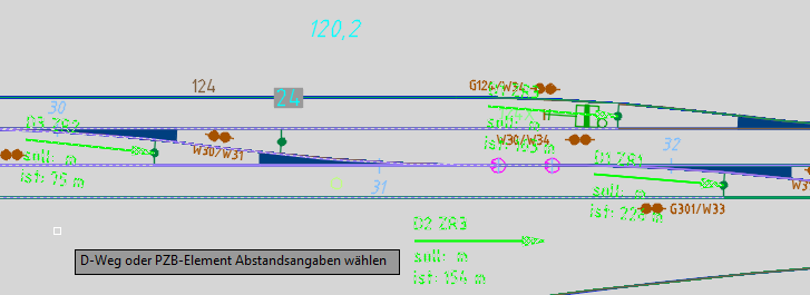
Illus.: Example for the selection of Overlap-distance indicators
3.After the object selection has been completed, the 'Referenzpunkt für Winkeleingabe wählen' prompt appears via the command line. The reference point can be defined by selecting any point in the drawing.
4.After selecting the reference point, the prompt 'Specify angle for insertion:' is issued via the command line. A temporary line to the mouse pointer is drawn from the reference point.
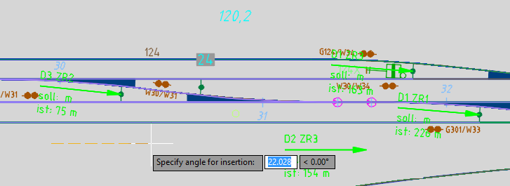
Illus.: Any reference point was selected
oThe angle can be determined by selecting a second point in the drawing or by entering an angle using the command line. When entering the angle using the command line, confirm the angle by pressing the Enter key.
oThe objects selected in step 2 are aligned according to the angle specification.
oThe names of the aligned distances are displayed in the command line.

Illus.: The Overlap-distance indicators have been aligned