Overlaps

Contents
Process:
•Planning of Overlaps and Distances to Danger Point
•Displaying and editing associated Switches of an Overlap
•Defining attributes for Overlaps
Requirements:
see Track Paths, Overlaps, Track Routes and Flank Protection
Description:
In ProSig, the Overlap is a PSO Area Object. Topological nodes (switches or crossings) do not interrupt the Overlap. When viewing the object attributes, a differentiation is made between overlaps and distances to danger points.
In the PlanPro glossary, the object is formulated as follows:
Overlap (Fstr_DWeg)
The Overlap is the secured track section behind the stop-indicating destination signal of a track path. It can be used for several track routes. No overlaps are to be provided for shunting roads. The overlap has to be distinguished from the safety distance and distance to danger point.
"The overlap begins at the stop-indicating destination signal and ends at a position markers (switch toe, limit of shunt indicator, opposite direction signal, track clearance section, etc.)." (Excerpt from Ril. 819.0202)
Distance to danger point (Fstr_DWeg)
The Distance to danger point is a secured track section between a stop-indicating entry signal, block signal or protecting signal and the danger point in case a train passes the signal due to insufficient braking (overlaps). The distance to danger point is represented by the overlap, the danger point is represented by the destination signal of the track path.
(Source: PlanPro Glossary)
Supporting video sequence:
Erstellung_DWeg.mp4 (Size: 7,5 MB)
Procedure:
1.To Create an overlap or distance to danger point, select the sub-tab 'Create' on the main tab 'Overlaps'.
To Display and edit the corresponding switches of an existing overlap continue with Step 8.
To Edit the attributes of an existing overlap, continue with Step 14.
Command Line: PRS_FAHRSTRASSE
Ribbon: ProSig EPU -> Equipment SCT -> Track Routes
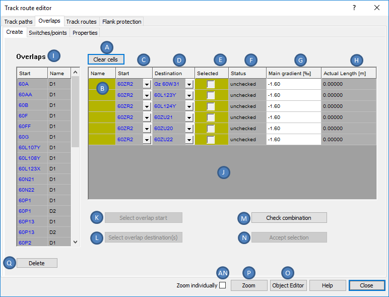
Illus.: Overlaps to be created with unchecked status
oIf overlaps or distances to danger points already exist in the planning project, then they are displayed in the list of 'Overlaps' (I). If no overlaps or distances to danger points are created, the list (I) will be empty.
oAfter selecting an object in the list (I), the attributes of the selected object can be displayed and edited by clicking the button 'Object Editor' (O). If several overlaps are selected in the list (I), the object attributes of all selected objects are displayed simultaneously.
oIf linked objects are marked in the list (J) (Columns 'Start', 'Destination'), the object attributes of these objects can be displayed by clicking the button 'Object Editor' (O).
oAfter selecting the objects in the list (I), the objects in the drawing can be marked and zoomed with the button 'Zoom' (P). The zoom can be set individually or together, depending on the setting of the check box 'Zoom individually' (AN).
oIf linked objects are marked in the list (J) (Columns 'Start', 'Destination'), the objects in the drawing can be marked and zoomed with the button 'Zoom' (P). The Zoom can be set individually or together, depending on the setting of the check box 'Zoom individually' (AN).
oAfter selecting Overlaps from the list (I), they can be deleted using the button 'Delete' (Q).
2.The Button 'Select overlap start' (K) is used to select the destination of a Track Path for an overlap. When planning distances to danger points, a home signal, block signal or protective signal needs to be selected. For planning an overlap of null behind dead-end track entry routes, select the fictitious destination signal of the dead-end track entry route (object attribute 'Operating Function' is set to 'ZZ (Zug-Ziel ohne Signal)'). Confirm the selection with the Enter key or click in the drawing.
oWhen the dialog is reopened, the selected starting point is displayed in the list of possible Start-/ Destination combinations (J) under the attribute 'Start' (C).
3.The Button 'Select overlap destination(s)' (L) is used to select a position marker in the drawing. As position markers you have to select a signal, a fouling point marker, a FMA-component or a facing end of a turnout (object switch component). When planning an overlap of null behind dead-end track entry routes, select the same fictitious destination signal as for the start.
oIf the calculated height points (requirement here is Creation of Gradient Data) are not considered in the gradient-dependent length calculation of the overlap, one or more corresponding points first have to be deselected (e.g. points on branch lines). If you do not want to deselect, press the Enter key.
oThen select the overlap destinations in the drawing. If you want to create several overlaps or distances to danger points at the same time, it is possible to select several objects. Confirm the selection with the Enter key.
oWhen the dialog is reopened, the selected destinations are displayed in the list of possible Start-/Destination combinations (J) under the attribute 'Destination' (D). If a fouling point marker is selected as the destination, and the corresponding switch lies within the overlap (fouling point marker behind switch toe), a separate Start-/ Destination combination is provided for each switch leg.
oThe Attribute 'Status' (F) of the possible Start-/ Destination combinations is currently 'unchecked'.
oThe Attribute 'Name' (B) is automatically assigned when a Start-/ Destination combination is selected and it can be adjusted if necessary.
oThe Attribute 'Main gradient [‰]' (G) is automatically assigned based on the gradient data stored in the ProSig project.
4.The Button 'Check combination ' (M) checks the possible Start-/ Destination combinations in list (J).
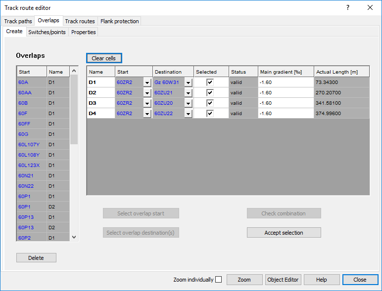
Illus.: Create an Overlap, checked
oThe Attribute 'Status' (F) is changed from 'unchecked' to 'valid' for valid Start-/ Destination combinations.
oInvalid Start-/ Destination combinations are no longer displayed.
oValid overlaps are automatically selected (E). Overlaps that should not be included in the project, have to be deselected.
oThe Attribute 'Actual Length [m]' (H) is filled automatically. The possible overlaps are displayed in ascending order according to the length of the overlaps.
5.With the button 'Accept Selection' (N), the selected overlaps are created.
oThe created overlaps are displayed in the list of Overlaps (I) with the name of the Start (C) and the name of the Overlap (B).
oThe overlap is a PSO and is stored as an area object during the creation on the Layer PRS-OVERLAP.
oThe overlap creates an overlap label in the drawing that marks the end of the overlap with an arrow (Layer PRS-OVERLAP-NAME). The details for the name of the overlap (Layer PRS-OVERLAP-NAME), nominal length (Layer PRS-OVERLAP-NOMINAL LENGTH [M]) and actual length (Layer PRS-OVERLAP-ACTUAL LENGTH [M]) are written on the arrow.
oThe function Align Distance Indicators is used to evenly align the distances of one or more overlaps.
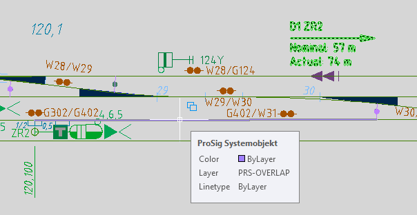
Illus.: Created Overlap in the drawing
6.After marking an overlap or distance to danger point in the list (I), the attributes of the selected object can be displayed by clicking the button 'Object Editor' (O). The display of the attributes differs depending on the selected object. If several objects are selected in the list (I), the attributes of all selected objects are displayed simultaneously.
 |
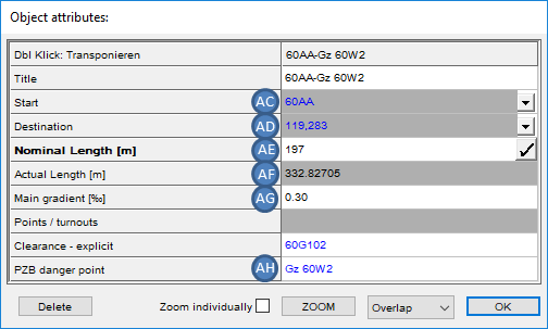 |
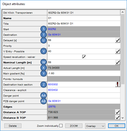
Illus.: Object Attributes of an Overlap |
Illus.: Object Attributes of a Distance to Danger Point |
oThe Attribute 'Start' (S, AC) contains a link to the object which is specified in Step 2 as the start of overlap or distance to danger point.
oThe Attribute 'Destination' (T, AD) contains a link to the object which is specified in Step 3 as the destination of the overlap or distance to danger point.
oThe value of the attribute 'Actual Length [m]' (X, AF) indicates the actual length of the overlap or distance to danger point, which is determined by 'Start' (S, AC) and 'Destination' (T, AD).
oThe value of the attribute 'Main gradient [‰]' (Y, AG) is based on the gradient data stored in the project and it is automatically calculated when the overlap is created.
oFor the attribute 'Nominal Length [m]' (W, AE), it is possible to automatically calculate the value by pressing the button with the exclamation mark at the right edge of the dialog box. The nominal length is calculated for the distances 50 meters, 100 meters and 200 meters from the overlap start based on the attribute 'Main gradient [‰]' (Y, AG). Enter the largest calculated value that is smaller than the value of ' Actual Length [m]' (X, AF).
oThe Attribute 'PZB danger point' (AB, AH) contains a link to an object position markers, which represents the PZB danger point.
oFor an overlap, the following additional attributes have to be filled:
▪The Attribute 'V Entry - Possible' (V) should be filled with the speed that results from the length of the overlap only. It is possible to have the value calculated automatically by pressing the button with the exclamation mark at the right edge of the dialog box. The automatically calculated Nominal Length (W) is used as the reference for the calculation, even if the value is edited manually.
▪For the attribute 'Destination track section' (Z), it is possible to have the value assigned automatically by pressing the button with the exclamation mark at the right edge of the dialog box.
▪For the attribute 'Delayed [s]' (U), it is possible to have the value calculated automatically by pressing the button with the exclamation mark at the right edge of the dialog box. The requirement is that the attribute 'Destination track section' (Z) is assigned, as the length of the destination track section is used for the calculation. A speed of 40 km/h is assumed. The calculation is based on Ril. 818 Section 5 (table on page 5066).
▪The Attribute 'Danger point' (AA) may be filled optionally and if necessary contains a link to an object position markers, which represents the danger point for an overlap.
7.Before creating Start-/ Destination combinations again, empty the list (H) with the button 'Clear cells' (A) (requirement for Step 1).
8.To set the attributes 'Locking' and 'Flank protection' of the associated switches of an overlap, select the sub-tab 'Switches/points' on the main tab 'Overlaps'.
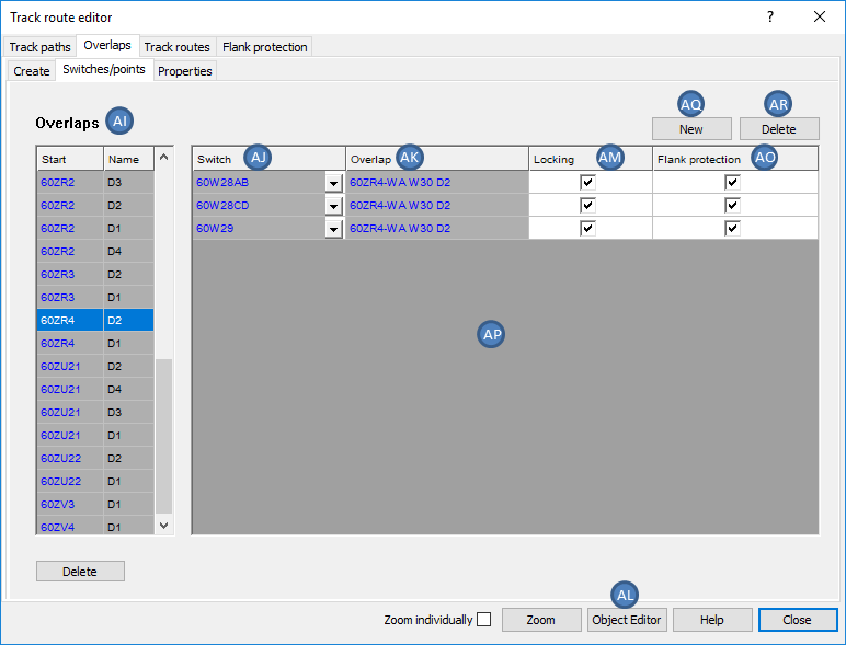
Illus.: Attributes of the associated Switches W 29 and Double slip 28 for an Overlap 60ZR4-WA W30 D2
9.After marking an overlap in the list (AI), the corresponding Overlap-Switch-Crossing combinations are listed in the list (AP), through which the overlap passes.
10.The Attributes of the displayed Overlap-Switch-Crossing combinations can be edited in list (AP).
oThe Attribute 'Switch' (AJ) contains a link to the object of the corresponding switch.
oThe Attribute 'Overlap' (AK) contains a link to the object of the overlap.
oThe Attributes 'Locking' (AM) and 'Flank protection' (AO) should be specified according to columns 9 to 12 in the table of overlaps.
11.When rows are selected in the list (AP), the button 'Object Editor' (AL) is used to open the object attributes of the corresponding switch elements for editing.
12.With the button 'New' (AQ), an additional switch can be assigned to a marked overlap in the list (AI) through the selection in the drawing. An object switch element should be selected.
13.After marking an overlap in the list (AI), the button 'Delete' (AR) is used to remove an assigned switch.
14.To Specify the assignments to Clearance - explicit and to the dependent key release instrument of an existing overlap or distance to danger point, select the sub-tab 'Properties' on the main tab 'Overlaps'.
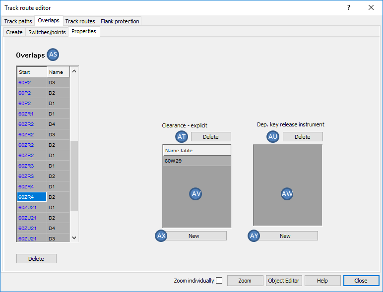
Illus.: Tab 'Properties' for the marked Overlap 60ZR4-WA W30 D2
15.In the list 'Overlaps' (AS), mark the overlap or distance to danger point for which the attributes will be defined.
16.With the button 'New' (AX), it is possible to assign an existing track clearance section in the drawing to the overlap or distance to danger point for the Clearance - explicit.
oOne or more Track clearance sections can be selected in the drawing. The selection is confirmed with the Enter key or by clicking in the drawing.
oAfter confirming the selection, the name of the track clearance section is displayed in the list (AV).
oThis attribute corresponds to column 13 of the table of overlaps.
17.After marking a track clearance section in the list (AV), the links for Clearance - explicit to an overlap or distance to danger point can be removed with the button 'Delete' (AT). The corresponding objects 'Track Clearance Section' will then remain in the drawing.
18.With the button 'New' (AY), it is possible to assign an existing dependent key release instrument to the marked overlap or distance to danger point.
oOne or more Key release instruments can be selected in the drawing. The selection is confirmed with the Enter key or by clicking in the drawing.
oAfter confirming the selection, the name of the key release instrument is displayed in the list (AW).
19.After marking key release instruments in the list (AW) the links as Dependent key release instrument to an overlap or distance to danger point can be removed with the button 'Delete' (AU). The associated objects 'Key Release Instrument' then remain in the drawing.