Planning the Intermittent Train Control

Contents
Prozess:
•Erstellen und Verwalten der PZB Zuordnungen zwischen PZB-Elementen und Signalen oder Weichenelementen
•Bearbeiten der Zuordnungen zum Bezugspunkt oder einer Fahrstraße
•Bearbeiten der INA-Eigenschaften
•Zuordnen von INA Gefahrstellen
Voraussetzung:
•ggf. INA-Berechnung
Beschreibung:
PZB-Elemente sind punktförmige PSO, die an der topologischen Kante verortet werden. PZB-Elemente können sowohl Gleismagnete als auch Geschwindigkeitsüberwachungseinrichtungen (GÜ) sein. Ein PZB-Element wird je nach Einstellung seiner Eigenschaften in der Projektzeichnung dargestellt.
Mit dem PZB/INA-Editor können über die Registerkarte 'PZB' Zuordnungen zwischen neuen oder bereits vorhandenen PZB-Elementen und einem PZB Bezugspunkt wie Signalen oder Weichenelementen erstellt und verwaltet werden. Die Zuordnung zu einer Fahrstraße (nur Zugstraßen) ist optional und fallbezogen notwendig. Die PZB-Elementzuordnungen sind logische Objekte.
Über die Registerkarte 'INA' können die INA-Eigenschaften der PZB-Elementzuordnungen ergänzt werden. Unter anderem kann das Dokument mit den Ergebnissen der INA-Berechnung als Anhang zugewiesen werden und eine INA Bahnsteigkante zugeordnet werden. Außerdem können den PZB-Elementzuordnungen INA Gefahrstellen zugeordnet und priorisiert werden.
Im PlanPro-Schema sind die Objekte wie folgt formuliert:
PZB-Element
(Bau)Art, Umfang und Funktionen der punktförmigen Zugbeeinflussung.
Unter dem PZB-Element werden sowohl einzelne Gleismagneten als auch die Geschwindigkeitsüberwachungseinrichtungen (GÜ - in der Literatur auch als Geschwindigkeitsprüfeinrichtungen - GPE bezeichnet) sowie dazugehörige Eigenschaften und Parameter zusammenfassend dargestellt.
DB-Regelwerk:
•819.1310 8 für Gleismagnete
•819.1310 9 für GÜ
In der Gleismagnettabelle finden sich die Angaben in den Zeilen 16 und 17 sowie 33 bis 35 für GÜ und 29 bis 32 für Gleismagnete.
PZB-Elementzuordnung
Zuordnung von einem PZB-Element zu einem Signal, einer Fahrstraße oder auch anderen Objekten, die im Bezug zum PZB-Element stehen.
Der Verweis von einem PZB-Element über das Zuordnungsobjekt auf ein Signal ist dabei immer gefüllt. Die Verknüpfung mit einer Fahrstraße (nur Zugstraßen sind relevant) oder weiteren Objekten (INA-berechnungsrelevante Objekte) ist fallbezogen notwendig.
Beispiel:
Verlinkung, zu welcher Fahrstraße der PZB-Gleismagnet gehört (wird nur angegeben, wenn Ziel der Fahrstraße nicht identisch mit zugeordnetem Signal ist oder Umfahrwege existieren). Dabei ist festgelegt, dass der Fahrweg der Fahrstraße über den PZB-Gleismagneten führt.
DB-Regelwerk:
Eintrag in der Gleismagnettabelle; die Zuordnung zu einzelnen Fahrstraßen wird heute über Fußnoten gelöst.
INA:
Der PZB-Magnet deckt gemäß Wirkbereichsbogen Bereiche ab.
Liegt ein Bahnsteig zwischen den PZB-Magneten von Vor- und nachfolgendem Hauptsignal, wird eine INA-Berechnung durchgeführt. Das Ergebnis wird in einem Wirkbereichsbogen dokumentiert. Daraus geht die Relevanz des PZB-Magneten für die Überwachung gegen Halt anfahrender Züge hervor, z. B.:
"Der GM 1000 Hz deckt bei bei einer Beschleunigung von 0,3 m/s² die Bereiche von ... bis ... m ab." oder "Der GM 2000 Hz deckt keine Bereiche ab".
Im Datenmodell werden INA-relevante Daten im Wesentlichen gespeichert im INA-Anhang.
INA-Berechnung:
Ermittlung sicher bzw. nicht sicher überwachter Startplätze anfahrender Züge am Bahnsteig.
Mit der PZB-Aufgabe "Anfahren gegen Halt zeigende Signale überwachen" soll jenes Risiko minimiert werden, das daraus resultiert, dass ein Zug nach einem Halt am Bahnsteig (auch beginnender Zug) gegen ein noch Halt zeigendes Signal anfahren kann. Deshalb betrifft die Funktion nur diejenigen Hauptsignale, die an oder hinter Bahnsteigen stehen, an denen planmäßig oder außerplanmäßig Reisezüge halten, beginnen oder wenden.
Im Gegensatz zu den anderen zwei PZB-Aufgaben ist beim unberechtigten Anfahren gegen ein Halt zeigendes Signal kein Durchrutschweg oder Gefahrpunktabstand gesichert. Deshalb muss die erste Stelle einer möglichen Gefährdung betrachtet werden. Als maßgebende Gefahrstelle kommen in Betracht:
•Spitze oder Grenzzeichen einer Weiche
•Bahnübergang oder höhengleicher Bahnsteigzugang
•Rangierhalttafel oder andere ortsfeste Rangier- und Schutzsignale der Gegenrichtung, wenn das zu betrachtende Hauptsignal ein Einfahrsignal ist
•Ende des Durchrutschweges, wenn sich innerhalb des Durchrutschweges keines der zuvor genannten Elemente befindet
Für die Beachtung der Aufgabe "Anfahren gegen Halt zeigende Signale überwachen" bei der PZB-Planung sind im Wesentlichen zwei Aufgaben zu lösen:
•PC-gestützte Ermittlung (INA-Berechnung; INA: Induktive Sicherung anfahrender Züge) des Erfordernisses und erforderlichenfalls der optimalen Lage eines 500 Hz-Gleismagneten (Regelverfahren)
•die an Belangen der Betriebssicherheit und Kundeninteressen ausgerichtete Festlegung der Halteplätze von Zügen
Zur Vorbereitung der INA-Berechnung sind zunächst die örtlichen Infrastrukturverhältnisse zu erheben. Diese können aus verlässlichen Planungen oder örtlichen Vermessungen bestehen und beinhalten Entfernungen zwischen dem 2000 Hz-Gleismagneten des betreffenden Bahnsteigsignals und
•Vorsignal(en)
•Vorsignalwiederholer(n)
•Bahnsteiganfang
•definierten Halteplätzen
•ggf. Zugdeckungssignalen
•Bahnsteigende
•ggf. bereits vorhandener 500 Hz-Gleismagnet(en)
•maßgebender Gefahrstelle
•ggf. schützenswertere(n) Gefahrstelle(n)
sowie weiteren relevanten Daten. Die Daten werden in einem Erhebungsbogen gespeichert. Außerdem sind die zugbezogenen Einflussparameter festzulegen. Diese ergeben sich aus der Art der Bremsen und der Beschleunigung der Fahrzeuge. Für jedes Betriebsprogramm werden typische Werte vorgegeben.
Im Datenmodell werden INA-relevante Daten im Wesentlichen gespeichert im INA-Anhang.
INA-Anhang
Dokument mit der INA-Berechnung zu einem Signal am entsprechenden Bahnsteig. Im LST-Datenmodell erfolgt die Abbildung in der PZB-Elementzuordnung.
(Quelle: PlanPro-Schema)
Unterstützende Filmsequenz:
Planen_der_punktförmigen_Zugbeeinflussung.mp4 (Größe: 8,9 MB)
Vorgehensweise:
1.Den PZB/INA-Editor starten und die Registerkarte 'PZB' wählen.
Zum Erstellen einer neuen PZB Zuordnung und gleichzeitigem Erzeugen eines neuen PZB-Elements weiter bei Schritt 2.
Zum Erstellen einer neuen PZB Zuordnung und Zuweisen eines vorhandenen PZB-Elements weiter bei Schritt 5.
Zum Erstellen weiterer PZB Zuordnungen zu einem Bezugspunkt oder zu einer Fahrstraße weiter bei Schritt 7.
Zum Bearbeiten der INA Eigenschaften und zum Festlegen der INA Gefahrstellen weiter bei Schritt 8.
Befehlszeile: PRS_PZB
Multifunktionsleiste: ProSig EPU -> Ausrüstung LST -> PZB/INA-Editor
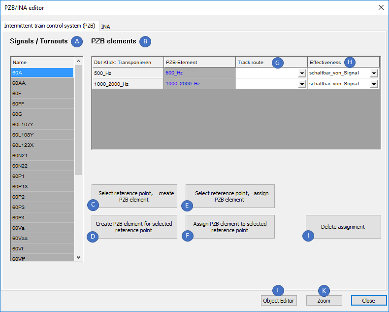
Bild: Registerkarte 'PZB' des PZB/INA-Editors
oSind im Planungsprojekt noch keine PZB-Elementzuordnungen zwischen Signalen / Weichenelementen und PZB-Elementen vorhanden, werden die Listen 'Signale / Weichen' (A) und 'PZB Zuordnungen' (B) leer angezeigt.
oSind im Planungsprojekt bereits PZB-Elementzuordnungen vorhanden, werden nach Markieren eines Objekts in der Liste 'Signale / Weichen' (A) die zugehörigen PZB Zuordnungen in der Liste 'PZB Zuordnungen' (B) angezeigt.
oBeim Erstellen einer neuen PZB Zuordnung wird automatisch eine Zuordnung zum Bezugspunkt in der Liste 'PZB Zuordnung Bezugspunkt' (C) erstellt. Zum Anzeigen des Objektes in der Liste (C) ist zunächst die zugehörige Zeile im Bereich 'PZB Zuordnungen' (B) zu markieren.
oDie Zuordnung zu einer Fahrstraße ist optional und wird nicht automatisch beim Erstellen einer PZB Zuordnung vorgenommen. Bei Bedarf kann zu einem PZB-Element eine zugehörige Fahrstraße in der Liste 'PZB Zuordnung Fahrstraße' (D) angegeben werden (wird nur angegeben, wenn das Ziel der Fahrstraße nicht identisch mit dem zugeordneten Signal ist oder Umfahrwege existieren). Dabei ist festgelegt, dass der Fahrweg der Fahrstraße über das PZB-Element führt. Ist die GÜ fahrstraßenabhängig, wird neben dem Symbol der Buchstabe F angeordnet, siehe hierzu auch Schritt 7.
oÜber die Schaltfläche 'Objekteditor' (E) werden die Eigenschaften zu einem im Dialog markierten Signal oder PZB-Element aus Liste (A) oder (B) angezeigt.
oMit der Schaltfläche 'Zoom' (F) wird ein im Dialog markiertes Objekt der Listen (A) oder (B) in der Zeichnung gezoomt.
2.Das Erstellen einer PZB-Elementzuordnung zwischen einem neuen PZB-Element und einem Signal oder Weichenelement kann über die Schaltflächen (G) oder (I) vorgenommen werden.
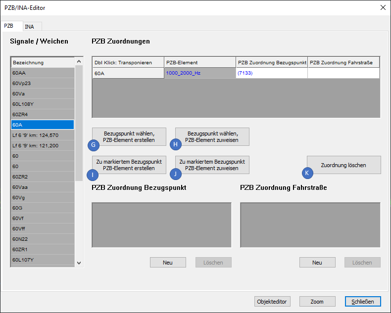
Bild: Registerkarte 'PZB' des PZB/INA-Editors - Erzeugen und Löschen von Zuordnungen
oÜber die Schaltfläche 'Bezugspunkt wählen, PZB-Element erstellen' (G) kann zu einem Signal oder Weichenelement in der Zeichnung ein neues PZB-Element in der Zeichnung erstellt werden.
oÜber die Schaltfläche 'Zu markiertem Bezugspunkt PZB-Element erstellen' (I) kann zu einem markierten Signal oder Weichenelement aus Liste (A) ein neues PZB-Element in der Zeichnung erstellt werden.
oWird beim Einfügen des PZB-Elements ein Signal gewählt, kann das PZB-Element direkt am Signal eingefügt oder optional durch Angabe eines Abstandes vom Signal aus an der topologischen Kante verschoben werden. Ein am Signal eingefügtes PZB-Element wird standardmäßig als Gleismagnet erstellt.
oWird beim Einfügen des PZB-Elements ein Weichenelement gewählt, ist zuerst ein Punkt auf einer topologischen Kante (Layer PRS-TOPOLOGISCHE KANTE) zu bestimmen. Anschließend kann das PZB-Element durch Angabe eines Abstandes von diesem Punkt aus an der topologischen Kante verschoben werden. Ein an der Weiche eingefügtes PZB-Element wird standardmäßig als Geschwindigkeitsüberwachungseinrichtung (GÜ) erstellt.
▪Wird eine GÜ beim Einfügen in der Zeichnung so positioniert, dass die Überwachung über eine Verzweigung der Gleislage hinweg stattfindet, werden je nach Anordnung automatisch mehrere GSE bzw. GSA an den zugehörigen Gleisen eingefügt.
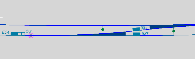
Bild: Automatische Darstellung mehrerer GSE beim Einfügen eines GÜ an einer Verzweigung
oSoll eine PZB-Elementzuordnung entfernt werden, ist zunächst das entsprechende Signal oder Weichenelement in der Liste (A) auszuwählen. Anschließend ist das zugehörige PZB-Element in der Liste (B) zu markieren. Nach Betätigen der Schaltfläche 'Zuordnung löschen' (K) wird die bestehende Zuordnung zwischen den markierten Objekten entfernt.
3.Nach dem Erstellen des PZB-Elements sind über die Funktion Objekt(e) editieren alle relevanten Daten einzugeben.
Befehlszeile: OE
Multifunktionsleiste: ProSig EPU -> Tools -> Objekt(e) editieren
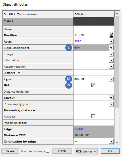 Bild: Eigenschaften eines PZB-Elements als 500Hz Gleismagnet |
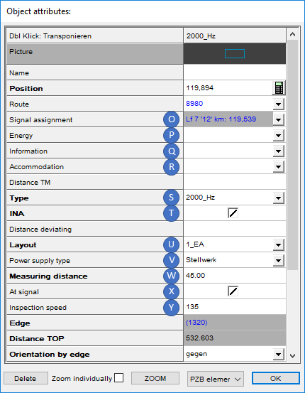 Bild: Eigenschaften eines PZB-Elements als Geschwindigkeitsüberwachung |
oDer Wert der Eigenschaft 'Signalzuordnung' (L, Q) enthält einen Link auf das beim Einfügen gewählte Signal oder Weichenelement und wird automatisch befüllt.
oDie Eigenschaften 'Energie' (M) und 'Information' (N) enthalten Informationen über den energetischen und logischen Anschluss des PZB-Elements. Die Eigenschaften sind nur zu befüllen, wenn es sich beim PZB-Element nicht um eine GÜ oder einen ständig wirksamer Gleismagneten handelt.
oDie Eigenschaft 'Art' (O, S) und 'Anordnung' (T) werden beim Erstellen des PZB-Elements automatisch belegt, können aber bei Bedarf im Nachgang manuell umgestellt werden. Die Eigenschaft 'Art' enthält die Frequenz und wird in der Zeichnung am PZB-Element angezeigt.
▪Beim Einfügen an einem Signal wird die Eigenschaft 'Art' (O) des PZB-Elements standardmäßig für einen Gleismagneten belegt. Die Frequenz des Gleismagneten wird je nach Art und Entfernung des gewählten Signals vorbelegt.
▪Beim Einfügen an einem Weichenelement werden die Eigenschaften 'Art' (S) und 'Anordnung' (T) das PZB-Elements standardmäßig für eine Geschwindigkeitsüberwachung (GÜ) belegt. Die Geschwindigkeitsüberwachung wird im Regelfall gemäß Variante 1 (Einschaltung - Wirkmagnet - Ausschaltung) angeordnet (Ril 819.1310).
oIst das PZB-Element relevant für die INA-Berechnung und deckt gemäß Wirkbereichsbogen Bereiche ab, ist die Checkbox für die Eigenschaft 'INA' (P) anzuhaken. Die Bearbeitung der INA-Eigenschaften wird in Schritt 8 näher erläutert.
oFür Geschwindigkeitsüberwachungen (GÜ) sind zusätzlich die folgenden Eigenschaften zu belegen:
▪Die Eigenschaft 'Unterbringung' (R) ist nur für eine GÜ zu befüllen - mit der Bedeutung: GÜ-Schaltkasten.
▪Für die Eigenschaft 'Bauart' (U) ist die Bauart der GÜ anzugeben.
▪Für die Eigenschaft 'Energieversorgung Art' (V) ist auszuwählen, wie die Energieversorgung der GÜ erfolgen soll.
▪Für die Eigenschaft 'Messstrecke' (W) ist die Länge der Messtrecke in Metern für die GÜ anzugeben. Die Darstellung der GÜ wird entsprechend in der Zeichnung aktualisiert.
▪Über die Eigenschaft 'Mitnutzung' (X) kann auf einen Gleismagneten am Signal verwiesen werden, wenn bei der Anordnung von GÜ unmittelbar am Signal der Wirkmagnet der GÜ und der Gleismagnet des Signals zu einem PZB-Magneten zusammengefasst werden sollen.
▪Für die Eigenschaft 'Prüfgeschwindigkeit' (Y) ist die an der GÜ eingestellte Überwachungsgeschwindigkeit in km/h einzutragen.
▪Für die Eigenschaft 'Messfehler' (Z) kann der Messfehlerbereich der GÜ in Abhängigkeit von der Bauart angegeben werden.
▪Für die Eigenschaft 'Prüfzeit [sek]' (AA) kann die Prüfzeit der GÜ in Abhängigkeit von der Bauart in Sekunden angegeben werden.
4.Nach dem Festlegen der Eigenschaften wird das PZB-Element in der Zeichnung je nach Einstellung der Eigenschaften dargestellt.
oDas PZB-Element ist ein punktförmiges PSO und wird auf dem Layer PRS-PZB-ELEMENT abgelegt.
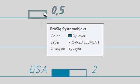
Bild: Darstellung des PZB-Elements in der Zeichnung
5.Das Erstellen einer PZB Zuordnung zwischen einem bereits vorhandenen PZB-Element und einem Signal oder Weichenelement kann über die Schaltflächen (H) oder (J) vorgenommen werden.
oÜber die Schaltfläche 'Bezugspunkt wählen, PZB-Element zuweisen' (H) können einem Signal oder Weichenelement in der Zeichnung ein oder mehrere bereits vorhandene PZB-Elemente zugeordnet werden.
oÜber die Schaltfläche 'Zu markiertem Bezugspunkt PZB-Element zuweisen' (J) können einem Signal oder Weichenelement aus Liste (A) ein oder mehrere bereits vorhandene PZB-Elemente zugeordnet werden.
6.Wurde ein PZB-Element in einem angegebenen Abstand vom Signal eingefügt, wird die PZB-Elementzuordnung durch das Objekt 'PZB Zuordnung Objekt' visualisiert. Dabei handelt es sich um einen Pfeil, der in die Richtung des Signals weist und an dem die Bezeichnung des zugehörigen Signals und der berechnete Abstand zu dem Signal dargestellt werden. Das Objekt 'PZB Zuordnung Objekt' ist ein PSO und wird auf dem Layer PRS-PZB ZUORDNUNG OBJEKT erstellt.
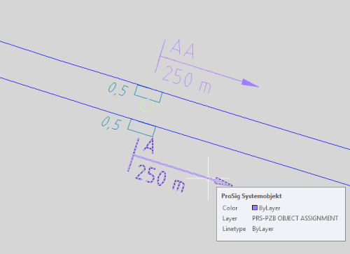
Bild: Darstellung von PZB-Zuordnungen in der Zeichnung
7.Nach dem Erstellen der PZB Zuordnung zwischen einem Signal oder Weichenelement und einem PZB-Element werden die PZB Zuordnungen und die Zuordnung zum Bezugspunkt in den Listen (B) und (C) im Dialog angezeigt. Zum Anzeigen und Bearbeiten des Objektes in der Liste (C) ist zunächst die zugehörige Zeile im Bereich 'PZB Zuordnungen' (B) zu markieren. Die Zuordnung zum Bezugspunkt ist immer zu erstellen und wird daher automatisch beim Anlegen einer PZB Zuordnung automatisch mit erzeugt.
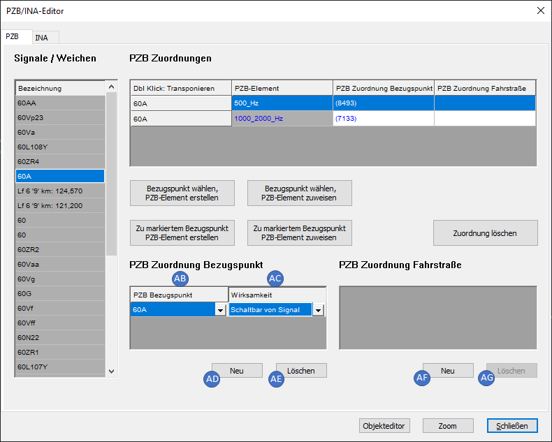
Bild: Registerkarte 'PZB' des PZB/INA-Editors - Bearbeiten von PZB Zuordnungen
oDie Eigenschaft 'PZB Bezugspunkt' (AB) wird nach dem Erzeugen der PZB Zuordnung automatisch mit dem gewählten Bezugspunkt befüllt.
oIn der Eigenschaft 'Wirksamkeit' (AC) ist anzugeben, ob das PZB-Element schaltbar ist und wie die Anschaltung erfolgt.
oÜber die Schaltfläche 'Neu' (AD) kann eine weitere Zuordnung zu einem Bezugspunkt erstellt werden.
oÜber die Schaltfläche 'Löschen' (AE) kann eine zuvor in der Liste (C) markierte Zuordnung zu einem Bezugspunkt gelöscht werden.
oSoll optional eine Zuordnung zu einer Fahrstraße erstellt werden, kann dieses über die Schaltfläche 'Neu' (AF) vorgenommen werden. Wurde die Fahrstraße im Dialog in der Liste 'PZB Zuordnung Fahrstraße' (D) ausgewählt, wird das PZB-Element in der Zeichnung anschließend mit dem Buchstaben F dargestellt.
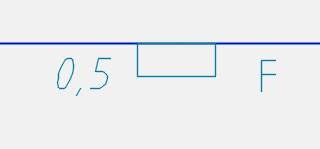
Bild: Darstellung eines fahrstraßenabhängigen
PZB-Elements in der Zeichnung
oÜber die Schaltfläche 'Löschen' (AG) kann eine zuvor in der Liste (D) markierte Zuordnung zu einer Fahrstraße gelöscht werden.
8.Über die Registerkarte 'INA' können die Eigenschaften der PZB-Elementzuordnungen bearbeitet und INA Gefahrstellen zugeordnet werden. Voraussetzung hierfür ist die Belegung der Eigenschaft 'INA' (P), wie in Schritt 3 - Eigenschaft 'INA' beschrieben.
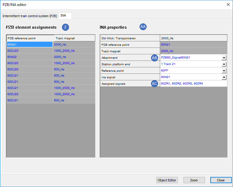
Bild: Registerkarte 'INA' des PZB/INA-Editors
oIn der Liste 'PZB-Elementzuordnungen' (AH) werden alle PZB Zuordnungen zu Bezugspunkten angezeigt, bei denen ein oder mehrere PZB-Elemente relevant für die INA-Berechnung sind.
oFür die Eigenschaft 'PZB Bezugspunkt' (AJ) wird automatisch der Verweis auf das Signal oder das Weichenelement eingetragen.
oÜber die Eigenschaft 'INA Anhang' (AK) sind ein oder mehrere Anhänge der INA-Berechnung anzugeben. Dazu gehören Erhebungsbogen, Wirkbereichsbogen und ggf. die Berechnungsblätter selbst. Die Zuordnung der Anhänge kann über Rechtsklick in das Wertefeld der Eigenschaft vorgenommen werden wie unter Editieren und Darstellen komplexer Daten - Zuordnen von Objekten mittels Dialog beschrieben. Hierfür sind zuvor über die Funktion Anhänge die erforderlichen Anhänge zu erstellen.
Befehlszeile: PRS_ANHANG
Multifunktionsleiste: ProSig EPU -> Planungsgrundlagen -> Anhänge
oÜber die Eigenschaft 'INA Bahnsteigkante' (AL) ist auf die zugehörige Bahnsteigkante bezogen auf ein Signale mit INA-Berechnung zu verweisen. Die Auswahl einer zuvor erstellten Bahnsteigkante ist über die Dropdownliste vorzunehmen. Die Bahnsteige sind zuvor über die Funktion Bahnsteige zu erstellen.
Befehlszeile: PRS_BAHNSTEIG
Multifunktionsleiste: ProSig EPU -> Planungsgrundlagen -> Bahnsteige
9.Nach Markieren einer Zeile der Liste (AH) werden die zugeordneten INA Gefahrstellen in der Liste 'INA Gefahrstelle' (AI) angezeigt.
oÜber die Eigenschaft 'Markanter Punkt' (AM) ist die Gefahrstelle für die INA-Berechnung anzugeben. Die Unterscheidung in maßgebende und schützenswertere Gefahrstelle erfolgt über die Eigenschaft 'Priorität Gefahrstelle' (AN).
oÜber die Eigenschaft 'Priorität Gefahrstelle' (AN) ist die Priorität der Gefahrstelle für die INA-Berechnung anzugeben. Für die maßgebende Gefahrstelle ist der Wert '1' einzutragen und für schützenswertere Gefahrstellen entsprechend höhere Werte.
oNach dem Markieren einer Zeile der Liste 'PZB Elementzuordnungen' (AH) kann über die Schaltfläche 'Neu' (AO) eine neue INA Gefahrstelle zu einer PZB-Elementzuordnung erzeugt werden.
oNach dem Markieren einer Zeile der Liste 'INA Gefahrstelle' (AI) kann die INA Gefahrstelle über die Schaltfläche 'Löschen' (AP) gelöscht werden.
10. Über die Eigenschaft 'Zugeordnete Signale' des Objektes 'PZB Zuordnung Objekt' können im Rahmen der INA-Berechnung Signale (Vorsignal, Vorsignalwiederholer, H-Tafel) zum maßgebenden 2000 Hz Gleismagneten des Hauptsignals zugeordnet werden.
oDie Zuordnung der Signale kann über Rechtsklick in das Wertefeld der Eigenschaft vorgenommen werden wie unter Editieren und Darstellen komplexer Daten - Zuordnen von Objekten oder Editieren und Darstellen komplexer Daten - Zuordnen von Objekten mittels Dialog beschrieben ist. Wurden der PZB Zuordnung bereits Signale zugeordnet über und sollen weitere Signale zugeordnet werden, sollte hier die Zuordnung von Objekten mittels Dialog verwendet werden.