Inserting FMA Feed-Ins and Feed-Outs

Contents
Process:
•Inserting FMA Feed-Ins and FMA Feed-Outs (FMA-IO) to supplement an FMA Component with components for input and output in track circuits.
Requirements:
Description:
In ProSig, the FMA-IO is a dot-like object located at the topological edge. Depending on the setting of the attributes 'Speiserichtung', the object is displayed in the drawing.
In the PlanPro glossary, the object is formulated as follows:
FMA-IO (FMA_Element)
Completion of an FMA Component in track circuits by the components for input and output. FMA Elements are directly assigned to the adjacent track clearance section to the right and/or left of the FMA Component.
The Object is not required for axle counter points.
DB Rules and Regulations:
•Type-specific Planning Information and Technical Notes;
•Planning data:
•Signalling layout plan, Level crossing plan,
•Track circuit wiring plan,
•Signaling block table.
(Source: PlanPro Glossary)
Procedure:
1.The Insertion of an FMA Feed-Ins/Feed-Outs can be performed with the function EPU-Object Inserter. Select the Object type 'FMA-IO'.
Command Line: PRS_EPU_EINF
Ribbon: ProSig EPU -> Equipment SCT -> EPU-Object Inserter
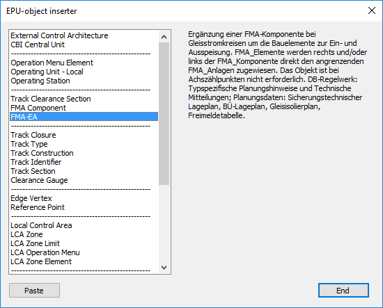
Illus.: Selection of the object type FMA-IO in the EPU-Object Inserter
2.The button 'Paste' is used to insert a new 'FMA-IO' object into the drawing. Select a point on the topological edge at which the corresponding track circuit is located.
oThe FMA-IO is a Dot-like PSO and has a graphical representative (circle) in the project drawing. The object is stored on the layer PRS-FMA-EA.
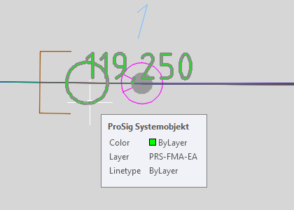
Illus.: Representation of an FMA-IO in the drawing
3.After insertion, all relevant data must be entered using the Edit Object(s) function.
Command Line: OE
Ribbon: ProSig EPU -> Tools -> Edit Object(s)
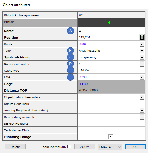
Illus.: Attributes of a FMA-IO with the Speiserichtung 'Einspeisung'
oA name for the FMA-IO can be specified for the Attribute 'Name' (A). If a name has been assigned, the Speiserichtung (C) must also be specified.
oFor the Attribute 'Type' (B), select the type of Feed-in or Feed-out into the Track clearance section. Further information can be found in the tool-tip.
oFor the Attribute 'Speiserichtung' (C), the feed direction must be selected if a description (A) has been assigned to the object. The assignment of the attributes 'Speiserichtung' determines the representation of the object in the drawing.
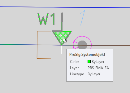
Illus.: FMA-EA with the Speiserichtung 'Feed Ins'
oFor the Attribute 'Number of Cables' (D), the number of rail connector ropes must be selected according to the application guidelines. The corresponding rope lengths are derived from the application guidelines and the type of the associated FMA system. If 'Other' is specified for the Number of Cables, a comment with corresponding explanations must be added for the value field.
oFor the Attribute 'Cable Type' (E), the cross-section and the material of the cables of the rail connectors must be entered according to the application guidelines, whereby the information is given in mm².
Examples: 120 Cu, 240 Al
oFor the Attribute 'FMA' (F), the associated FMA system must be assigned either via the drop-down list or via right-click in the value field of the attribute, menu item 'Assign object(s)' and subsequent selection of a corresponding object in the drawing, see also Editing And Displaying Complex Data - Assigning Objects.