General Dialog for Inserting ProSig System Objects

Contents
Process:
•Insert ProSig system objects that are not created using separate editors.
Requirements:
•The Requirements for inserting the individual object types can be found in their processes.
Description:
The Dialog EPU-Object Inserter offers a wide selection of object types for insertion into the project drawing. The inserted objects are ProSig System Objects (PSO). The descriptions of the respective object types can be found in their processes:
Object Type |
Process Description |
|---|---|
External Control Architecture |
Creating the External Control Architecture with the EPU Object Inserter |
CBI Central Unit |
|
Operation Menu Element |
|
Operating Unit - Local |
|
Operating Station |
|
Track Clearance Section |
Inserting of Track Clearance Section with the EPU Object Inserter |
FMA Component |
|
Track Type |
|
Track Construction |
|
Track Identifier |
|
Track Section |
|
Clearance Gauge |
|
Edge Vertex |
|
Reference Point |
|
Local Control Area |
|
LCA Zone |
|
LCA Zone Limit |
|
LCA Operation Menu |
|
LCA Zone Element |
|
Technical Field |
|
Technical Point |
|
Switching Device(s) |
|
Signal-Fictitious |
|
Line |
|
Chainage Axis |
|
Accommodation |
|
Sensor |
1.Start the EPU-Object Inserter and select the desired object type.
Command Line: PRS_EPU_EINF
Ribbon: ProSig EPU -> Equipment SCT-> EPU-Object Inserter
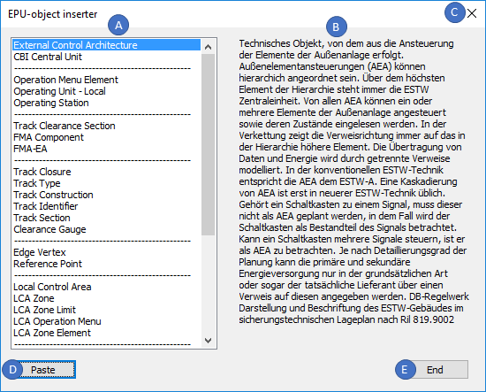
Illus.: Dialog EPU- Object Inserter, Example External Control Architecture
oThe object types that can be inserted into the project drawing via the EPU Object Inserter are listed in area (A).
oThe object description (PlanPro-specific) for a selected object type is displayed in area (B).
2.The 'Paste' button (D) can be used to insert an object of the selected object type into the project drawing.
oWhen inserting the object, the corresponding process description and the descriptions for PSO Area Object - Insert or Dot-like PSO - Insertion must be observed.
oThe inserted object is a PSO and is stored on the corresponding PSO Layer.
3.The dialog can be closed with the buttons 'End' (E) or 'X' (C).
4.After insertion, all relevant data must be entered using the Edit Object(s) function.
Command Line: OE
Ribbon: ProSig EPU -> Tools -> Edit Object(s)
oThe assignment of the object attributes can be found in the process description of the inserted object type.