Insertion of Platforms

Contents
Process:
•Insertion of Platform, Platform Edge and Platform Access with the Platform Editor.
Requirements:
•Platform Planning
Description:
In ProSig, the logical object Platform consists of the following objects:
•One or more Platform Edges (Area Object)
•One or more Platform Accesses (Dot-like Object)
The Area object platform edge is located to the left or right of the topological edge (Layer PRS-TOPOLOGICAL EDGE), and has the shape of a double line with a constant system height. If there is a height difference on a platform, then another platform edge with a different system height is defined to this platform.
The Dot-like Object platform access is represented by an arrow on the platform. This object is marked through the access type and location and is always represented to the right of the topological edge (Layer PRS-TOPOLOGICAL EDGE).
In the PlanPro glossary, the objects for representing platform system, platform edge and platform access are formulated as follows:
Platform (Bahnsteig_Anlage)
A Civil engineering element located parallel to the track with a paved surface for the purpose of access by passengers to and from trains.
A Platform can have one or more platform edges. There can be more than two platform edges attached to a platform, e.g. if a tongue platform is attached to a central platform.
DB Rules and Regulations: Ril 813.0201
Platform Edge (Bahnsteig_Kante)
An Edge of a platform parallel to the track, which is usable for the passenger exchange.
For SCT planning, the start and end of the platform edge used are decisive, e.g. for train control (PZB 90) and the definition of signal locations and danger points.
The installation length of the platform edge is represented in the data model by the length of the area object platform edge. Eventually, the following civil engineering objects (also disused platform areas) can be mapped as engineering structures (not yet modeled).
DB Rules and Regulations: Representation of a Double Line in the Signalling Layout Plan
Platform Access (Bahnsteig_Zugang)
Passenger's access point to the platform.
The middle of the line on which the access path meets the platform is always specified.
In order to use it in the Signalling layout plan during editing, a new symbol is created. This symbol should not appear in the final layout plan.
In SCT Planning, the access is relevant for the INA calculation. The point on the platform edge at which the inflow of passengers will take place is required. This point is not saved in the data model. It can be derived from Bahnsteig_Zugang.
DB Rules and Regulations: Access is mentioned in the INA data entry form, location is not yet determined.
(Source: PlanPro Glossary)
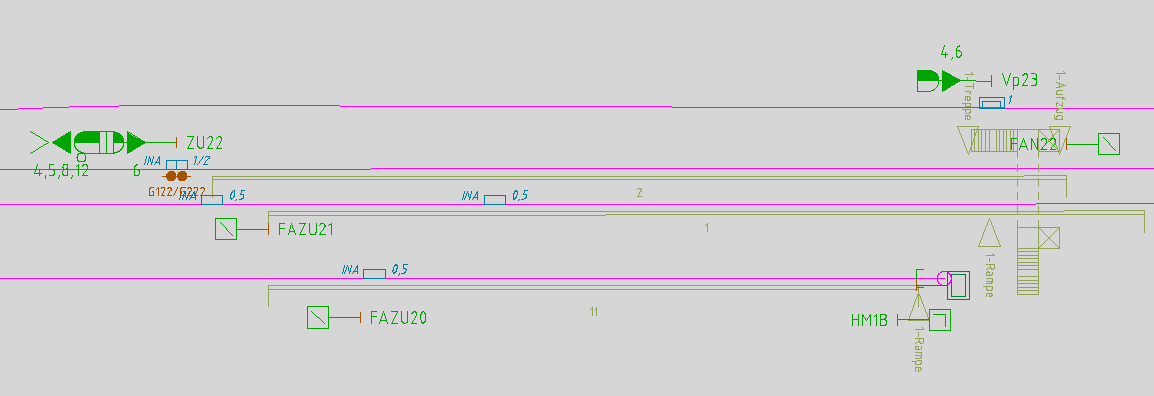
Illus.: Representation of Platforms with their Platform Edges and Platform Accesses in the Drawing
Supporting video sequence:
Einfuegen_von_Bahnsteigen.mp4 (Size 5,24 MB)
Procedure:
1.Start the Platform Editor.
Command Line: PRS_BAHNSTEIG
Ribbon: ProSig EPU -> Planning Basis -> Platforms
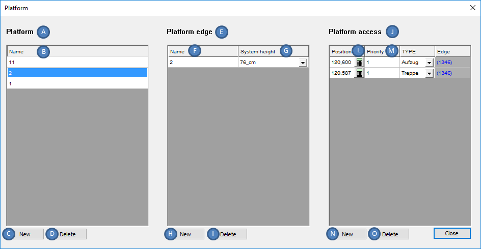
Illus.: Creation of Platforms, Platform Edges and Platform Accesses with the Platform Editor
2.The Button 'New' (C) is used to create a new logical object Platform.
oThe object Platform is not displayed in the drawing.
oThe newly created object platform is automatically appended to the end of the list (A) as an empty field.
3.For the Attribute 'Name' (B) of the platform, the name of the platform can be specified by following the instructions in the tool tip.
4.In the List (A), select the platform object for which a platform edge is to be created.
oA Platform can have one or more platform edges (for example, two platform edges per platform for a central platform).
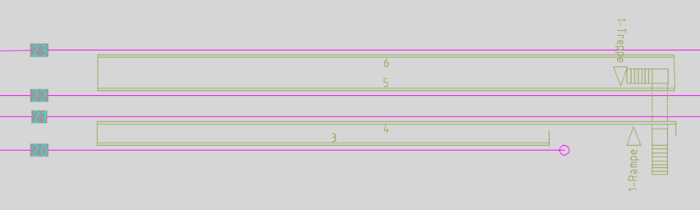
Illus.: Example platforms with several platform edges (Platform between tracks 20 and 21 with associated platform edges 3 and 4 and platform between tracks 22 and 23 with associated platform edges 5 and 6)
5.With the Button 'New' (H) a new object platform edge can be created, which is assigned to the marked platform. The boundary points of the platform edge on the topological edge (Layer PRS-TOPOLOGICAL EDGE) have to be specified in the drawing.
oOnly the first two specified points are analyzed (Start and End of a Platform Edge).
oFor the direction of the platform edge (attribute 'Direction of Edge' (R)), the order of the selection is decisive when specifying the boundary points.
oFor the representation of the platform edge to the left or right of the topological edge, the value of the attribute 'Lateral distance' (Q) should be modified accordingly, after closing the platform editor using the function Edit Object(s). To change the orientation, enter a negative value.
Command Line: OE
Ribbon: ProSig EPU -> Tools -> Edit Object(s)
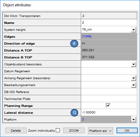
Illus.: Attributes of a Platform Edge
oThe Platform Edge is displayed in the drawing after closing the Platform Editor.
oThe distance of the platform edge from the topological edge (Q) is 1.0 ZE by default.
oThe newly created, empty object platform edge is automatically appended to the end of the list (E).
6.For the Attribute 'Name' (F), the name of the platform edge should be specified.
7.For the Attribute 'System height' (G), the height of the platform edge can be specified according to the information in the tool tip.
8.To create the platform access to a platform, select the corresponding platform object in the list (A).
9.With the Button 'New' (N) a new object platform access can be created, which is assigned to the marked platform. A point for the platform access on the topological edge (layer PRS-TOPOLOGICAL EDGE) should be specified in the drawing. Hints for insertion are described in ProSig System Objects - Insertion of Dot-like Objects.
oThe Platform Access is represented in the drawing after closing the Platform Editor.
oThe Distance of the platform access from the topological edge (Attribute 'Lateral distance' (U)) is 2.0 ZE by default.
10.After the insertion of the platform access and the closing of the platform editor, all relevant data should be entered using the function Edit Object(s).
Command Line: OE
Ribbon: ProSig EPU -> Tools -> Edit Object(s)
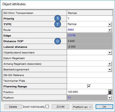
Illus.: Attributes of a Platform Access
11.The Value of the attribute 'Priority' (L, S) is the priority of the Platform access.
12.The Value of the attribute 'TYPE' (M, T) is the access type of the Platform access.
13.The Graphical representation of stairways and elevators can be designed using the classic Auto CAD functions.
14.In order to delete a Platform, press the 'Delete' button (D) after selecting a platform from the list (A). The corresponding objects 'Platform Edge' and 'Platform Access' are automatically deleted during this process.
15.In order to delete a Platform Edge, press the 'Delete' button (I) after selecting a platform edge in the list (E).
16.In order to delete a Platform Access, press the 'Delete' button (O) after selecting a Platform Access.