Insertion of Cable Cabinets into the Cable Overview Plan

Contents
Process:
•Insertion of Cable cabinets, Cable distribution box, Cable junction box and the Interlocking into the Cable overview plan.
Requirements:
Description:
In order to perform the cabling in the Cable overview plan, first insert the Cable cabinets, Cable distribution box, Cable junction box, the MSTT or the Interlocking into the Cable overview plan. The representations are purely symbolic and have no connection to the Concrete parts in the Cable layout plan.
Procedure:
1.Start the function 'Main Module' to create the Cable Overview Plan.
Command Line: KUP_HPT
Ribbon: ProSig EPU -> Wiring -> Cable Overview Plan -> Main Module
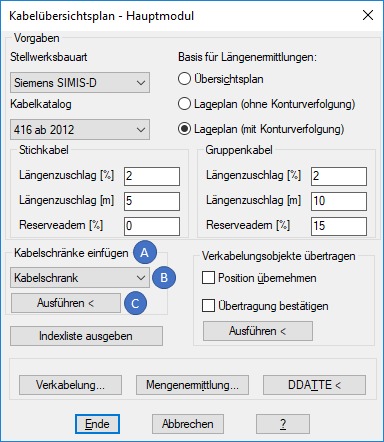
Illus.: Section for inserting the Cable Cabinets
2.In the section 'Insert cable cabinets' (A), it is possible to select the type of object to be inserted and then insert it into the Cable overview plan.
oUse the drop-down to select the Cable cabinet (B), to define the type of object to be inserted. The following types are available:
Nr. |
Type |
Number of terminals |
Notes |
|---|---|---|---|
1 |
Cable cabinet |
0/0/0/840 |
|
2 |
Distribution box |
0/0/0/240 |
|
3 |
Cable junction box 1 |
0/0/0/240 |
|
4 |
Cable junction box 2 |
0/0/0/240 |
|
5 |
Cable junction box 3 |
0/0/0/240 |
|
6 |
Interlocking |
0/0/0/20000 |
|
7 |
MSTT |
0/0/0/100 |
only selectable for Interlocking type Simis D |
Table: List of Object types in the section 'Insert cable cabinets'
oClick the button 'Start <' to insert the selected object into the drawing.
▪If the screen is divided into exactly two view ports, it is necessary to identify the view ports at the first automatic change. By selecting an object in the corresponding view port, the Cable overview plan is defined. When actions are subsequently executed, then the program knows which view port is intended for the Cable layout plan and which for the Cable overview plan.
▪For positioning in the Cable overview plan, the object snap is automatically switched off and the grid snap is set.
▪'Select insertion point' - The insertion point should be specified. If there is a grid of auxiliary lines, as described under Setting Up the Cable Overview Plan, Step 1, select the lowest point of a longer drawn auxiliary line. For Cable cabinets, Cable junction box 2, Cable junction box 3, Interlocking and MSTT, the selected point corresponds to the beginning of the lowest cable.
▪'Input height of cable cabinet or identify by selecting point on screen (Y-coordinate corresponds to highest cable):' - The height of the cable cabinet can be determined by selecting it in the drawing or by entering the drawing units.
▪The created object is NOT a PSO, but a Block. The object has no connection to the equivalent concrete parts in the Cable layout plan.
▪The Object is stored on Layer 42445.
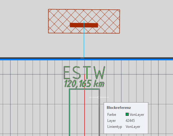
Illus.: Representation of a Cable Cabinet in the drawing using the example of a Interlocking
3.After the insertion, the attributes of the block have to be edited, for example with the AutoCAD functionalities DDATTE or ATTEDIT.
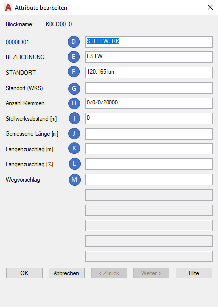
Illus.: Attributes of a Symbol for the Interlocking in the Cable Overview Plan
oThe Attribute '0000ID01' (D) should not be edited. This is the ID attribute of the block. The ID provides information about the type of object, determines the automatic object handling and it is the basis for calculations.
oFor the Attribute 'BEZEICHNUNG' (E), the name of the object should be specified. In the drawing of the object, this is displayed as a visible attribute.
oThe Attribute 'STANDORT' (F) is automatically assigned, if the Option 'Overview plan' is selected as the basis for length determination during Defining the Defaults. However, there is no automatic assignment if the basis for length determination is a layout plan. However, the location can be selected from the corresponding concrete part in the Cable layout plan and filled manually. In the drawing of the object, the location information is displayed as a visible attribute.
oThe Attribute 'Standort (WKS)' is automatically assigned and analyzed if the Option 'Overview plan' is selected as the basis for the length determination during Defining the Defaults. This is the calculated position in WCS Coordinates.
oThe Attribute 'Anzahl Klemmen' (G) contains the terminal specification in format A/B/C/D with the following equivalents:
▪A = Number of cores in use
▪B = Number of reserve cores
▪C = Number of defective cores
▪D = Maximum number of terminals
The Attribute are automatically assigned/updated.
oThe Attribute 'Stellwerksabstand [m]' are automatically assigned to '0', if the associated object has the ID 'STELLWERK'.
oThe Attributes 'Gemessene Länge [m]' (J), 'Längenzuschlag [m]' (K), 'Längenzuschlag [%]' (L) and 'Wegvorschlag' (M) are not used.