Inserting an Edge Vertex with the EPU Object Inserter

Contents
Process:
•Inserting an Edge Vertex with the EPU-Object Inserter.
Requirements:
Description:
In ProSig, an Edge Vertex is a dot-like object that can be inserted into schematic plans to modify the topological representation.
Information on using Edge Vertex can be found on the page Erzeugen und Anpassen der Topologie, Schritt 2.
Procedure:
1.The Insertion of an Edge Vertex into an Overview Plan can be performed with the function EPU-Object Inserter. Select the Object type 'Edge Vertex'.
Command Line: PRS_EPU_EINF
Ribbon: ProSig EPU -> Equipment SCT-> EPU-Object Inserter
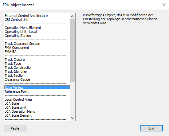
Illus.: Selection of the object type Edge Vertex in the EPU Object Inserter
2.With the button 'Paste' a new object 'Edge Vertex' can be inserted into the drawing. A point on the topological edge is to be selected, at which the course of the edge is to be adapted.
oThe Edge Vertex is a Dot-like PSO and receives a graphical representative (circle) in the project drawing. The object is stored on the PRS-EDGE VERTEX layer.
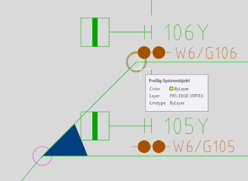
Illus.: Representation of a Edge Vertex in the drawing
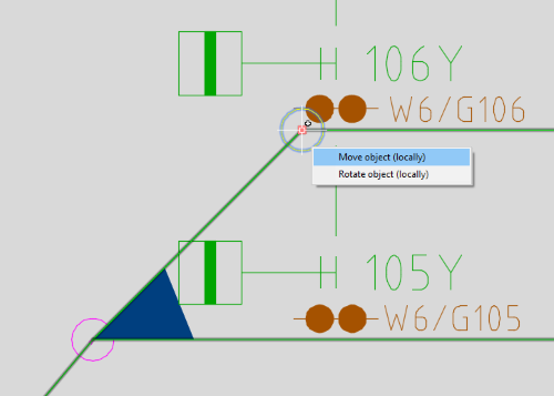
3.To Modify the topological representation, the Edge Vertex must be marked. By selecting the Menu item 'Move object (local)' the Edge Vertex can be moved, see also ProSig System Objects - PSO - Move / Rotate.
 |
 |
Illus.: Marked Edge Vertex with Selection Menu |
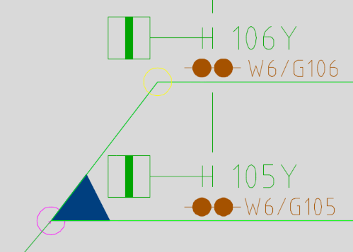
Illus.: Topological representation after moving the Edge Vertex |
oThe representation of Area objects is automatically adapted to the progression of the modified topological edge.