Insertion of Switches, Crossings and Slip Switches

Contents
Process:
•Insertion of Switches, Crossings and Slip Switches.
Requirements:
Description:
Switches, Crossings and Slip Switch in ProSig system consist of the logical object Switch system and the dot-like objects Switch element and Switch component. There is no switch system for Derailers. Depending on the position of the topology, the objects can be inserted at the corresponding topological nodes or edges with the respective functions.
In the PlanPro glossary, the objects that represent the Switch system, Switch element and Switch component are formulated as follows:
Switch System (W_Kr_Anlage)
Constructional totality of the objects switch or crossing including the positioning, control and checking devices available for its function directly or in the nearby.
Typical Basic forms of Switch Systems are:
•Ordinary Point (EW),
•Single Slip (EKW),
•Double Slip (DKW),
•Rigid crossing (KR)and
•Movable point crossings with double frog and movable point frog (KR).
The designations are based on Ril 800.0120 in connection with the associated systems.
Switch systems are divided into the individual elements (switch element). The elements have one or more components (switch components). These objects describe further attributes (e.g. Drives and Point detector contact) of the switch system in connection with standard drawings.
DB Rules and Regulations: Ril 800.0120
Switch Element (W_KR_Gsp_Element)
An individually adjustable part of a switch system or a derailer which can assume a maximum of two positions (direction of travel right or left respectively derailer device is retracted or lowered).
Switch systems are assigned 1 or 2 switch elements. Each switch element consists of at least one (possibly more than one) components (Point ends, Movable point frog), which represent the technical view.
A Crossing has two switch elements (A- and B-side). In the case of movable double frog, the crossing also have two end positions.
A Rigid crossing has no standard drawing as it does not have a drive.
Derailers do not have an object within the system.
The Attribute groups GZ_Freimeldung_R or GZ_Freimeldung_L are only specified when the right or left leg of a switch is not released without fouling point marker.
If the element is not utilized for a switch or track barrier (e.g. Bolting of a movable bridge or gate), the attribute groups Gleissperre_Element and Weiche_Element are not used (optional choice). The refinement of the modeling takes place after version 1.8.0.
DB Regulations: Switches are built according to guideline 800.0120. There are standard drawings of Group S 73xx for the arrangement of the components (including drives) on a switch and for the derailers.
For the planning of switches, the set of rules
•819
to note.
Switch Component (W_KR_Gsp_Komponente)
Movable part of a switch elements of a switch or derailer (e.g. point ends, derailer device, bolting of externally movable elements) or the constructive midpoint of a crossing in the form of 2 crossing sides.
In the topological model, the switch component as a dot-like object is used to create the link with the node. The switch nodes are defined as assignment points for topology and topography. The location of the switch component is represented for the typical use cases in the modeling of switches. For ordinary points, a switch node corresponds to the facing end of a point. For Single slip and Double slip both the switch node corresponds to the beginning of the corresponding point ends (also here uniformly described as facing end of a point).
At a Slip switch (adjustable and non-adjustable) the midpoint of the slip switch is used as a switch node. Both crossover sides are located at the two crossing topological edges. The midpoint of an diamond crossover is neither a topological node nor a GEO node.
For Derailers, the position of the derailer device is located. The lateral position in the object point determines the rail to which the derailer device is attached. The lateral position refers to the direction of the topological edge and does not represent the derailment direction!
The Signal is modeled as a separate object signal, when the switch component has to be equipped with a (switch) signal which is not mechanically connected with the switch (e.g. Spring switch signal, switch position indicator).
The Switch position indicator of a double slip is controlled by the two switch elements, but displayed in a signal. Therefore it is only modeled as a signal in the switch system.
When the attribute switch signal is set, a switch signal mechanically connected to the switch component is established according to the standard drawing. In that case, no separate signal is modeled.
In the glossary, the attributes 'Radius-Left' and 'Radius-Right' marked with (E) should no longer be filled, due to a future omission.
(Source: PlanPro Glossary)
Procedure:
1.The Insertion of switches is performed with the Function 'Switches'.
Command Line: PRS_WEICHE_EINF
Ribbon: ProSig EPU -> Planning Basis -> Switches/Crossings -> Switches
oTo insert a switch, select a topological node (meeting point of three edges) in the drawing.
oThe inserted switch is a PSO and consists of the logical object Switch System, a Switch Element and a Switch Component.
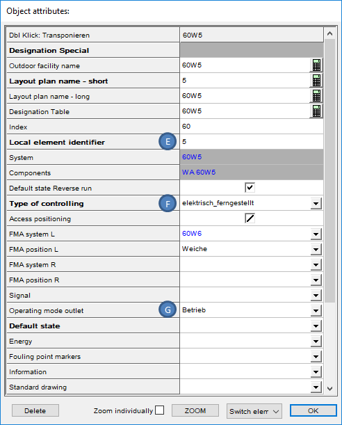
▪The Object switch element is displayed depending on the assignment of the attribute 'Type of controlling' (F, I) in the drawing. The switch element is stored on the layer PRS-SWITCH ELEMENT.
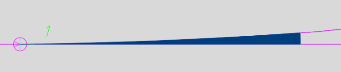
Illus.: Representation of an Ordinary Point (electrically remote operated) in the drawing
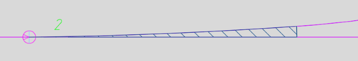
Illus.: Representation of an Ordinary Point (electrically locally controlled) in the drawing
▪The Object switch component is automatically displayed when the switch is inserted, depending on the topology, either for an ordinary point or for an curved point. The switch component is stored on the layer PRS-SWITCH COMPONENT.
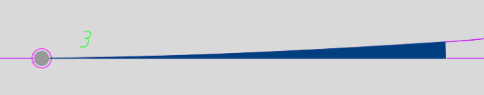
Illus.: Representation of a Curved point in the drawing
oTo fill the attributes of the objects corresponding to the switch, continue with Point 4.
2.The Insertion of crossings is performed with the function 'Crossings'.
Command Line: PRS_KREUZUNG_EINF
Ribbon: ProSig EPU Planning Basis -> Switches/Crossings -> Crossings
oFor the insertion of crossing, first select the intersection point between two topological edges in the drawing. Then select two points one after the other on the edges where element A ends approx.
oThe inserted crossing is a PSO and consists of the logical object Switch System, two Switch Elements and two Switch Components.
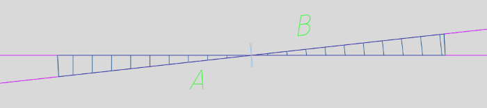
Illus.: Representation of a Crossing in the drawing
oTo fill the attributes of the objects corresponding to the crossing, continue with Point 4.
3.The Insertion of Slip switches (Single slip and Double slip) is performed with the function 'Slip Switches'.
Command Line: PRS_KREUZUNGSWEICHE_EINF
Ribbon: ProSig EPU -> Planning Basis -> Switches/Crossings -> Slip Switches
oTo insert an Single slip, two topological nodes A and B have to be selected. Confirm the selection e.g. with Enter.
oThe inserted Single slip is a PSO and consists of the logical object Switch system, two Switch elements and two Switch components.
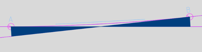
Illus.: Representation of a Single Slip in the drawing
oTo insert a Double slip, select four topological nodes in the node sequence A to D.
oThe inserted Double slip is a PSO and consists of the logical object Switch system, two Switch elements and four Switch components.
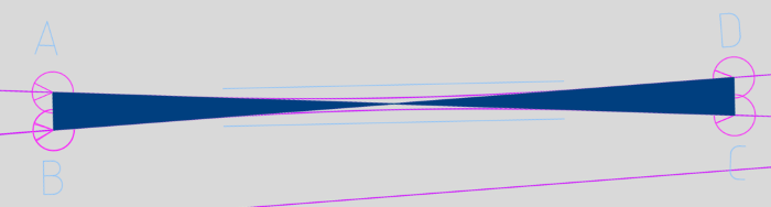
Illus.: Representation of a Double Slip in the drawing
4.After the insertion, all relevant data are entered using the function Edit Object(s).
Command Line: OE
Ribbon: ProSig EPU -> Tools -> Edit Object(s)
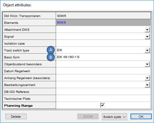 Illus.: Attributes of Switch system of an Ordinary Point |
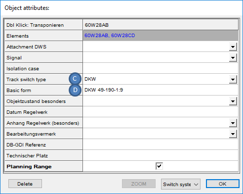 Illus.: Attributes of Switch Component of a Double Slip |
oThe Attribute 'Track switch type' (A, C) is automatically assigned when inserting the switch, crossing or slip switch and if necessary it can be adjusted.
oThe Attribute 'Basic form' (B, D) is manually assigned with the basic switch form. The assignment of this attribute impacts the length of the switch in the drawing.
 Illus.: Attributes of a Switch Element of an Ordinary Point |
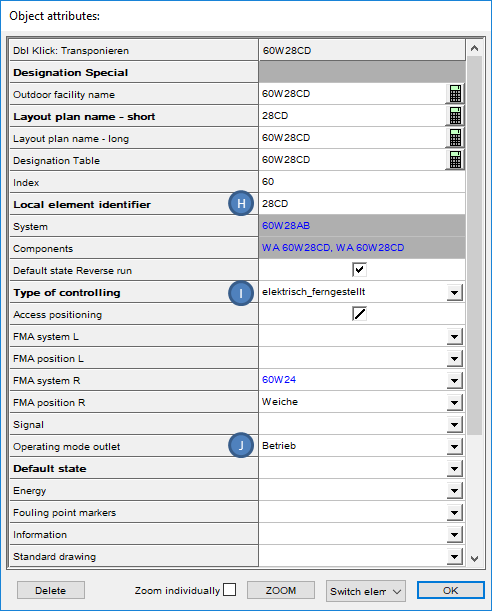 Illus.: Attributes of a Switch Element of a Double Slip |
oIn the Attribute 'Local element identifier' (E, H) the name of the switch needs to be entered.
oThe Attribute 'Type of controlling' (F, I) is used to define the control type of the switch element. The assignment of this attribute impacts the representation of the switch in the drawing.
oThe Attribute 'Operating mode outlet' (G, J) is automatically assigned and if necessary, it can be adjusted.
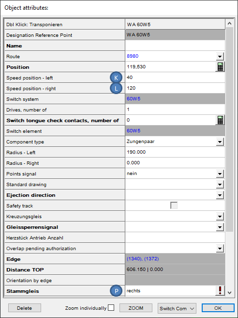 Illus.: Attributes of a Switch Component of an Ordinary Point |
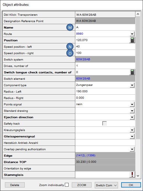 Illus.: Attributes of a Switch Component of a Double Slip |
oThe Attribute 'Name' (M) is only relevant for Single Slip and Double Slip and is automatically assigned the values A to D during insertion.
oThe Attributes 'Speed position - left' (K, N) and 'Speed position -right' (L, O) are filled with the permitted speeds over the respective switch legs in km/h.