Creation of the Cable Layout

Contents
Process:
•Creating the Cable layout plan and positioning the Concrete parts in the Cable layout plan.
Requirements:
•Deriving further Layout Plans
Description:
After assigning a cable layout plan to the project and automatically adjusting the safety-related elements, it is possible to set up the cable layout plan. In order to determine the cable lengths later during the cabling of the elements in the cable overview plan, first create the cable routes, cable cabinets and if necessary, the MSTT in the cable layout plan.
Procedure:
1.The Cable routes are displayed along with the track layout.
oThey can be derived from an existing cable route plan or generated manually.
oPolylines are used to display the cable routes, which are generally offset by one to two drawing units next to the track layout.
oThe Polyline should be broken open, when a cable route branches off.
2.The Insertion of the Concrete Parts can be performed with the function Cable Route Plan.
Command Line: KABEL_LP
Ribbon: ProSig EPU -> Wiring -> Cable Route Plan
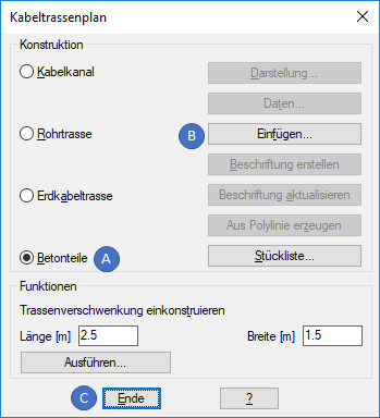
Illus.: Dialog for inserting the Concrete parts
oAfter selecting the Option Concrete Parts (A), the button 'Insert' (B) activates the dialog 'Choose concrete part', where the type of concrete part to be inserted can be determined.
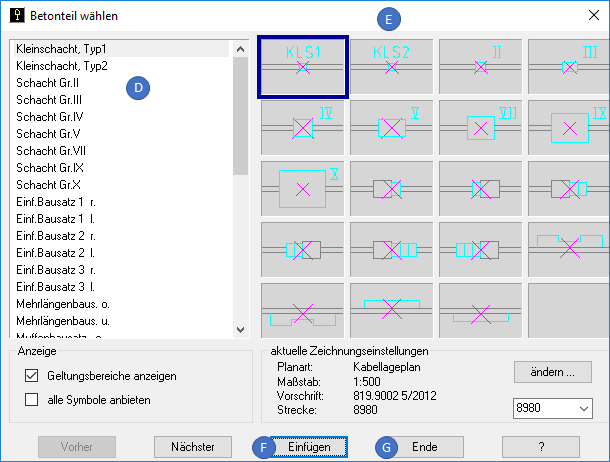
Illus.: Determining the type of Concrete parts to be inserted
oThe required concrete part can be selected using the designation in the List (D) or the preview in the List (E).
oThe Button 'Insert' (F) can be used to insert the selected concrete part into the drawing. When inserting, select a point in the drawing that corresponds to the physical location of the concrete part.
oAfter inserting the concrete part, the dialog 'Choose concrete part' is activated again and another concrete part can be inserted. The dialog can be closed with the button 'Finish' (G).
oThe Dialog 'Cable Route Plan' can be closed with the button 'Finish' (C).
3.For all safety-related elements to be wired, the Troughs for the Tail cable should be constructed.
oThe Construction of the stitches can be done using polylines.
oThe Cable routes do not end directly at the safety-related elements.
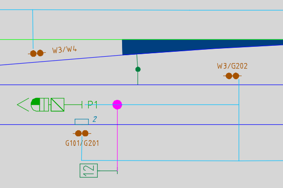
Illus.: Example for the construction of manholes for Tail cables
oThe Polylines should be broken at the branches.
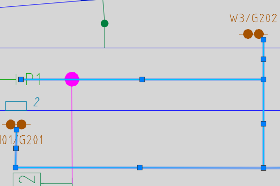
Illus.: The Marker displays the broken polylines at the branches