Editing the Speed Data

Contents
Prozess:
•Erstellen und Bearbeiten der Geschwindigkeitsdaten
Voraussetzung:
•Automatisches Erstellen der ETCS Gleiskanten
Beschreibung:
Der Geschwindigkeitswechsel wird in ProSig als punktförmiges Objekt dargestellt. Die Geschwindigkeitswechsel sind die Begrenzungspunkte der Geschwindigkeitsprofile und enthalten Informationen zu Kilometer und Strecke.
Das Geschwindigkeitsprofil wird in ProSig als Bereichsobjekt zwischen den Geschwindigkeitswechseln erzeugt. Die Eigenschaft 'Wirkrichtung bezogen auf Kilometrierung' wird hierbei standardmäßig mit dem Wert 'Beide' belegt. Für richtungsabhängige Geschwindigkeiten sind für den entsprechenden Bereich stattdessen manuell zwei Geschwindigkeitsprofile zu erzeugen, ein Profil mit der Wirkrichtung 'In' und eines mit der Wirkrichtung 'Gegen'.
Die Geschwindigkeitsprofile können entweder automatisch anhand der in den Weichenkomponenten eingetragenen Geschwindigkeiten oder manuell erzeugt werden. Für Bereiche der Gleislage in denen die Geschwindigkeitswechsel auf einer topologischen Kante eingefügt wurden, sind die Geschwindigkeitsprofile manuell zu erzeugen.
In PlanPro ist das Objekt wie folgt formuliert:
Geschwindigkeitsprofil
Zulässige Geschwindigkeit der Strecke, bei ETCS auch außerhalb der durchgehenden Hauptgleise. Das Geschwindigkeitsprofil wird zusammengesetzt aus Bereichen mit konstanten Geschwindigkeiten. Es kann in unterschiedlichen Arten (z. B. NeiTec, ETCS) ausgeprägt sein. Für jede Art wird ein separates Geschwindigkeitsprofil angelegt. 'Geschwindigkeitsband' ist ein Synonym für Geschwindigkeitsprofil. Unabhängig vom Geschwindigkeitsprofil können in Elementen (Weiche, Gleisabschnitt) eigenen Geschwindigkeiten hinterlegt sein. Je nach Anwendung wird über die Gültigkeit der in den Elementen hinterlegten Geschwindigkeit oder der des Geschwindigkeitsprofils entschieden.
(Quelle: PlanPro-Modell)
Vorgehensweise:
1.Die Funktion 'Bändereditor' starten.
Befehlszeile: PRS_BAENDER
Multifunktionsleiste: ProSig EPU -> Ausrüstung ETCS -> Bändereditor
2.Die Registerkarte 'Geschwindigkeit' auswählen.
Zum manuellen Erstellen von Geschwindigkeitswechseln weiter bei Schritt 3.
Zum manuellen Erstellen von Geschwindigkeitsprofilen weiter bei Schritt 7.
Zum automatischen Erzeugen von Geschwindigkeitswechseln und Geschwindigkeitsprofilen anhand eingetragener Geschwindigkeiten von Weichen weiter bei Schritt 9.
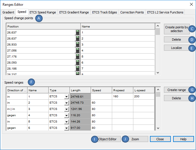
Bild: Bändereditor - Registerkarte 'Geschwindigkeit'
3.Mit der Schaltfläche 'Punkte durch Auswahl erstellen' (B) können Geschwindigkeitswechsel durch Auswahl in der Zeichnung erstellt werden.
oBeim Einfügen können ein oder mehrere Punkte auf der topologischen Kante (Layer PRS-TOPOLOGISCHE KANTE) gewählt werden. Die Auswahl ist mit der Eingabetaste zu bestätigen.
oDie Geschwindigkeitswechsel werden nach dem Einfügen mit ihren relevanten Eigenschaften am Ende der Liste (A) angezeigt.
oDer Geschwindigkeitswechsel ist ein PSO-Punktobjekt.
oNach dem Erzeugen wird der Geschwindigkeitswechsel auf der Gleislage dargestellt und auf dem Layer PRS-GESCHWINDIGKEITSWECHSEL abgelegt.
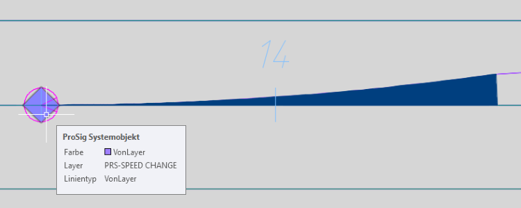
Bild: Geschwindigkeitswechsel in der Zeichnung
4.Nach dem Einfügen eines Geschwindigkeitswechsels sind über die Objekteigenschaften alle relevanten Daten einzugeben. Hierfür stehen mehrere Möglichkeiten für die Eingabe zur Verfügung:
oDirekte Dateneingabe über die Eigenschaften in der Liste (A).
oMarkieren eines Geschwindigkeitswechsels in der Liste (A) und Betätigen der Schaltfläche 'Objekteditor' (J) (siehe auch Schritt 13).
oNach dem Schließen des Bändereditors kann die Funktion Objekt(e) editieren auf den Geschwindigkeitswechsel in der Zeichnung angewendet werden.
Befehlszeile: OE
Multifunktionsleiste: ProSig EPU -> Tools -> Objekt(e) editieren
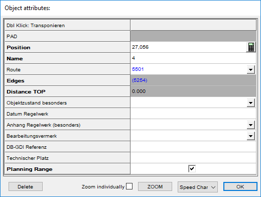
Bild: Eigenschaften eines Geschwindigkeitswechsels
5.Mit der Schaltfläche 'Verorten' (D) können Geschwindigkeitswechsel, die nicht automatisch beim Einfügen verortet wurden, ihrer topologischen Kante zugeordnet werden.
1.Schaltfläche 'Verorten' (D) wählen.
2.Geschwindigkeitswechsel in der Zeichnung wählen, der verortet werden soll.
3.Topologische Kante wählen, an welcher der Geschwindigkeitswechsel verortet werden soll.
4.Die Punkte 5.2 und 5.3 wiederholen, bis alle Geschwindigkeitswechsel verortet sind.
5.Beenden der Funktion mit der Eingabetaste.
oMit dem Report zur Verortung kann die Verortung von Geschwindigkeitswechseln überprüft werden.
Befehlszeile: VERORTE_REPORT
Multifunktionsleiste: ProSig EPU -> Tools -> Dienste -> Report zur Verortung
▪Nicht verortete Geschwindigkeitswechsel liegen meist nicht exakt auf der Topologie. Durch lotrechtes Schieben auf die Topologie werden sie verortet.
▪Die Geschwindigkeitsprofile in der Umgebung eines nicht verorteten Geschwindigkeitswechsels müssen optisch überprüft werden. Da wo die Topologie (Layer PRS-TOPOLOGISCHE KANTE) nicht durch Geschwindigkeitsprofile (PRS-GESCHWINDIGKEITSPROFIL) abgedeckt ist, müssen ggf. falsche Profile gelöscht und durch die richtigen ersetzt werden.
6.Für die Erstellung eines Geschwindigkeitsprofils (Schritt 7) werden zwei Geschwindigkeitswechsel benötigt. Entsprechend sind die Schritte 3, 4 und ggf. 5 erneut auszuführen.
7.Mit der Schaltfläche 'Profil erstellen' (F) kann ein Geschwindigkeitsprofil manuell in der Zeichnung erstellt werden.
oEs sind zwei Geschwindigkeitswechsel in der Zeichnung zu wählen, zwischen denen auf der topologischen Kante eine Verbindung besteht. Diese Verbindung darf nur in eine Richtung (also ohne Umkehrung) laufen.
oWurde das Geschwindigkeitsprofil erstellt, wird es in der Liste (E) mit seinen Eigenschaften angezeigt.
oDas Geschwindigkeitsprofil ist ein PSO-Bereichsobjekt.
oNach dem Erzeugen wird das Geschwindigkeitsprofil als Bereichsobjekt auf der Gleislage dargestellt und auf dem Layer PRS-GESCHWINDIGKEITSPROFIL abgelegt.

Bild: Geschwindigkeitsbereich in der Zeichnung
8.Nach dem Erstellen des Geschwindigkeitsprofils sind über die Objekteigenschaften alle relevanten Daten einzugeben. Hierfür stehen mehrere Möglichkeiten für die Eingabe zur Verfügung:
oDirekte Dateneingabe über die Objekteigenschaften in der Liste (E).
oMarkieren eines Geschwindigkeitsprofils in der Liste (E) und Betätigen der Schaltfläche 'Objekteditor' (J) (siehe auch Schritt 13).
oNach dem Schließen des Bändereditors kann zum Bearbeiten der Objekteigenschaften die Funktion Objekt(e) editieren auf das Geschwindigkeitsprofil in der Zeichnung angewendet werden.
Befehlszeile: OE
Multifunktionsleiste: ProSig EPU -> Tools -> Objekt(e) editieren

Bild: Eigenschaften eines Geschwindigkeitsprofils mit richtungsunabhängiger Geschwindigkeit

Bild Eigenschaften zweier Geschwindigkeitsprofile für richtungsabhängige Geschwindigkeit
oFür die Eigenschaft 'Anzeigegeführte ES Kategorie' (L) ist die Kategorie anzugeben (z. B. Gültigkeit für Reise- oder Güterzüge), sofern die Art des Geschwindigkeitsprofils mit dem Wert 'anzeigegeführt ES' befüllt wurde.
oDie Eigenschaft 'Wirkrichtung bezogen auf Kilometrierung' (M, R) ist mit der für die die Geschwindigkeit (O, S) geltenden Wirkrichtung in Bezug auf die Kilometrierung zu befüllen.
▪Liegt keine Richtungsabhängigkeit für die Geschwindigkeit vor, ist für das Profil die Eigenschaft 'Wirkrichtung bezogen auf Kilometrierung' (M) mit dem Wert 'Beide' zu befüllen.
▪Liegt eine Richtungsabhängigkeit für die Geschwindigkeit vor, sind zwischen den entsprechenden Geschwindigkeitswechseln zwei Geschwindigkeitsprofile zu erstellen.
Die Eigenschaft 'Wirkrichtung bezogen auf Kilometrierung' (R) ist in diesem Fall für das Geschwindigkeitsprofil in aufsteigender Kilometrierungsrichtung mit dem Wert 'In' und für das Geschwindigkeitsprofil in absteigender Kilometrierungsrichtung mit dem Wert 'Gegen' zu befüllen. Die Geschwindigkeit (S) kann anschließend für jedes der Geschwindigkeitsprofile und somit für jede Richtung separat eingetragen werden.
oDie Eigenschaft 'Art des Geschwindigkeitsprofils' (N) ist mit der Art des Geschwindigkeitsprofils zu befüllen.
oDie Eigenschaft 'Geschwindigkeit' (O, S) ist mit der zulässigen Geschwindigkeit für das Geschwindigkeitsprofil zu befüllen. Die Geschwindigkeit der Profile wird im ETCS-Übersichtsplan über das ETCS Geschwindigkeitsband visualisiert.
oDie Eigenschaften 'Anfangsgeschwindigkeitswechsel' (P) und 'Endgeschwindigkeitswechsel' (Q) enthalten Verweise auf die Geschwindigkeitswechsel zwischen denen das Geschwindigkeitsprofil erstellt wurde.
9.Mit der Schaltfläche 'Profile automatisch erstellen' (I) können sowohl Geschwindigkeitswechsel als auch Geschwindigkeitsprofile automatisch erstellt werden.
oVoraussetzung für das automatische Erzeugen der Objekte ist, dass zuvor in den Weichenkomponenten die Geschwindigkeiten für den linken und rechten Strang der Weiche hinterlegt wurden und anschließend die ETCS Knoten und ETCS Gleiskanten erzeugt wurden.
oDie Geschwindigkeit (O) wird für das ausgewählte Geschwindigkeitsprofil anschließend automatisch ermittelt und eingetragen, kann jedoch manuell editiert werden.
oDie Geschwindigkeitswechsel werden automatisch auf allen Weichenknoten erzeugt.
oWurden zuvor Geschwindigkeitswechsel manuell auf einer topologischen Kante und nicht auf einem Weichenknoten eingefügt wie in Schritt 3 beschrieben, werden zu diesem Geschwindigkeitswechsel keine angrenzenden Geschwindigkeitsprofile erstellt. Diese sind manuell zu erstellen, siehe auch Schritt 7.
oDie automatisch erstellten Geschwindigkeitsprofile werden nur richtungsunabhängig erstellt. Liegt eine Richtungsabhängigkeit für die Geschwindigkeit vor, ist so vorzugehen wie unter Schritt 8 für die Eigenschaft 'Wirkrichtung bezogen auf Kilometrierung' (R) beschrieben ist.
10. Mit der Schaltfläche 'Geschw. aus Weichen zuweisen' (H) kann nach Auswahl eines Geschwindigkeitsprofils aus der Liste (E) die Geschwindigkeit automatisch anhand der eingetragenen Geschwindigkeiten der Weichenkomponenten ermittelt werden. Ggf. zuvor manuell eingetragene Geschwindigkeiten (O, S) werden hierbei durch den automatisch ermittelten Wert ersetzt.
11. Mit der Schaltfläche 'Löschen' (C) kann ein markierter Geschwindigkeitswechsel gelöscht werden. Ist der Geschwindigkeitswechsel einem Geschwindigkeitsprofil zugeordnet, wird dieses ebenfalls gelöscht.
1.Markieren eines Objekts im Dialogbereich 'Geschwindigkeitswechselpunkte' (A).
2.Die Schaltfläche 'Löschen' (C) auswählen.
3.Der markierter Geschwindigkeitswechsel wird aus der Liste (A) entfernt und aus der Zeichnung gelöscht.
Das oder die zugehörigen Geschwindigkeitsprofile werden aus der Liste (E) entfernt und aus der Zeichnung gelöscht.
12. Mit der Schaltfläche 'Löschen' (G) kann ein markiertes Geschwindigkeitsprofil gelöscht werden.
1.Markieren eines Objekts im Dialogbereich 'Geschwindigkeitsprofile' (E).
2.Die Schaltfläche 'Löschen' (G) auswählen.
3.Das markierte Geschwindigkeitsprofil wird aus der Liste (E) entfernt und aus der Zeichnung gelöscht.
13. Mit der Schaltfläche 'Objekteditor' (J) können die Eigenschaften eines markierten Objektes angezeigt und bearbeitet werden.
1.Markieren eines Objekts im Dialogbereich 'Geschwindigkeitswechselpunkte' (A) oder 'Geschwindigkeitsprofile' (E).
2.Die Schaltfläche 'Objekteditor' (J) auswählen.
3.Die Eigenschaften des markierten Objekts werden zur Bearbeitung angezeigt.
14. Mit der Schaltfläche 'Zoom' (K) kann ein markiertes Objekt in der Zeichnung markiert und gezoomt werden.
1.Markieren eines Objekts im Dialogbereich 'Geschwindigkeitswechselpunkte' (A) oder 'Geschwindigkeitsprofile' (E).
2.Die Schaltfläche 'Zoom' (K) auswählen.
3.Das markierte Objekt wird in der Zeichnung markiert und gezoomt.