Align Objects

Contents
Process:
•Align Prosig system objects to the corresponding topological edge.
Requirements:
Description:
With the function 'Align objects', one or more existing, dot-like ProSig system objects in the project drawing can be re-aligned from the insertion point at the topological edge at which they are located. When aligning, the lateral position, working direction and lateral distance from the topological edge can be redefined. If several objects are selected, only objects with the same location point at the topological edge are aligned.
Procedure:
1.Start the function 'Align Objects’.
Command Line: AUSRICHT
Ribbon: ProSig EPU -> Tools -> Services -> Align Objects
oAfter calling the function, the prompt 'Auszurichtende Objekte wählen - Bezugsobjekt als erstes' and 'Select objects:' are issued via the command line.
oOnly dot-like PSO's located at a topological edge or block references can be aligned. PSO's inserted in the free drawing area (e.g. accommodation), PSO's located at several edges (e.g. fouling point marker) or area objects are ignored during further processing of the function.
2.Select the objects in the drawing that you want to align.
oFirst selected object is a PSO: If several PSO's are selected, the function verifies whether they have the same location point at the topological edge. Only PSO's located at the same point on the topological edge can be aligned together. The first object selected is the reference object. The object selection can be terminated with the Enter key or by pressing the right mouse button. The further procedure for aligning PSO is described under Step 3 and Step 4.
oFirst selected object is a Block reference: Block references can be aligned with a line. As an option, the block references can be moved before alignment. If several drawing elements are selected, the first object selected is used as the reference object. When aligning, the object group is rotated around the base point of the reference object.
3.Align PSO: When the command line prompt 'Specify lateral position and working direction:' appears, select a point in one of the displayed quadrants. The selection determines the new position of the objects to be aligned.
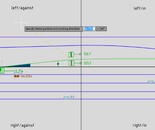
Illus.: Determining the position and working direction of a dot-like, localized PSO during insertion
Selection in the quadrant |
Impact on the object |
right |
Object is inserted to the right of the topological edge. |
left |
Object is inserted to the left of the topological edge. |
in |
The object is inserted in the direction of the topological edge (working direction = in). |
against |
Object is inserted against the direction of the topological edge (working direction = against). |
Middle between left and right |
The object is inserted exactly in the middle of the topological edge. |
Middle between in and against |
Object is assigned the working direction = both. |
Middle between in/against and left/right |
Object is inserted exactly in the middle of the topological edge and gets the working direction = both. |
| Table: User options for lateral position/working direction when aligning and the corresponding impact on the dot-like PSO |
4.Align PSO: When the command line prompt 'Enter lateral distance in meters: <Value for distance>:' appears, the distance of the objects from the topological edge can be redefined separately for each object.
oThe distance value must be entered as positive. The objects are repositioned at the specified distance from the topological edge according to the previously defined position and working direction.
5.Align Block reference: In the command line prompt 'Punkt auf Element für Ausrichtung wählen' it is necessary to select a point on the element at which the selected drawing elements have to be aligned (e.g. a Line).
6.Align Block reference: In the command line prompt 'Input rotation angle:' the angle should be specified by selecting a point in the drawing or by entering a value. The selected drawing elements are rotated accordingly around the base point of the reference object.