Assigning the ETCS Range

Contents
Process:
•Assigning the ETCS Range
Requirements:
•Inserting ETCS Track Equipment (Data Points)
Description:
In ProSig, the ETCS Range is an Area object that is inserted in the Signalling layout plan. Subsequently, the ETCS Overview plan is displayed according to Ril 819.1344 by thicker lines for contents within this ETCS Range.
Procedure:
1.Start the function 'Ranges Editor'.
Command Line: PRS_BAENDER
Ribbon: ProSig EPU -> Equipment ETCS -> Ranges Editor
2.Select the tab 'ETCS L2 Service Functions'.
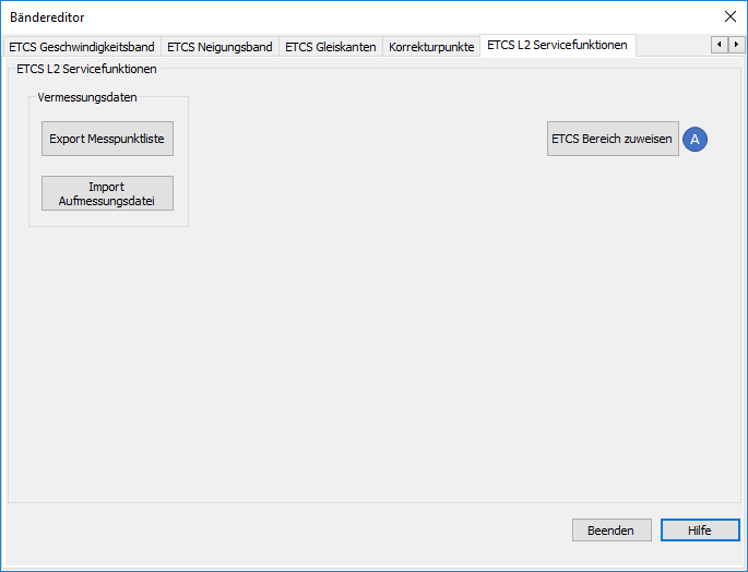
Illus.: Ranges Editor - Tab 'ETCS L2 Service Functions'
3.With the button 'Assign ETCS range' (A), an ETCS Range can be inserted into the drawing.
oDuring the insertion, select the boundary points of the range on the topological edge ( Layer PRS-TOPOLOGICAL EDGE). Exit the selection with the Enter key.
▪If several track paths between the boundary points are available, it is recommended to select intermediate points to uniquely identify the ETCS range.
oThe ETCS Range is a PSO-Area Object.
oAfter the creation, the ETCS Range is displayed as an Area object on the track layout and stored on the Layer PRS-ETCS RANGE.
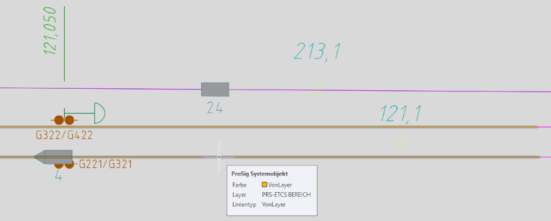
Illus.: Representation of the ETCS Range consisting of several sub-ranges in the drawing
4.An ETCS Range can consist of several sub-ranges. Repeat the Steps 1 to 3. The further selected sub-ranges are added to the existing ETCS Range.