Defining Project attributes and Pre-settings
(in Bearbeitung)
Prozess:
•Festlegung von Vorbelegungen für einige Eigenschaften neu eingefügter Objekte über die Projekteigenschaften
Voraussetzungen:
•Erstellen der Außenelementansteuerungen
Beschreibung:
Einige der im Projektobjekt definierten Eigenschaften gelten als Vorgabewerte für später eingefügte LST-Objekte und werden in deren Eigenschaften übernommen. Ein Großteil dieser Vorgabewerte kann bereits im Vorfeld festgelegt werden, siehe auch Einrichten des Planungsprojektes. Die Information zur aktuellen Außenelementansteuerung kann allerdings erst nach dem Erstellen des zugehörigen Objekts ergänzt werden.
Vorgehensweise:
1.Eigenschaften des Projektobjektes öffnen.
Befehlszeile: PRS_OEP
Multifunktionsleiste: ProSig EPU -> Tools -> Projektobjekt editieren

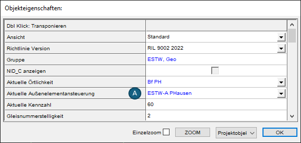
Bild: Eigenschaften des Projektobjektes
2.Die Eigenschaft 'Aktuelle Außenelementansteuerung' (A) wird bei der Erstellung neuer Objekte im Projekt als Vorgabewert für die Objekteigenschaften 'Energie' und 'Information' genutzt und automatisch übernommen, sofern das Objekt diese Eigenschaften besitzt. Für den Fall, dass einzelne Objekte einer anderen Außenelementansteuerung zuzuordnen sind, kann der Wert im Objekt separat geschaltet werden. Sind im Projekt unterschiedliche Außenelementansteuerungen anzugeben, kann vor Bearbeitung des entsprechenden Bereichs der zugehörige Wert im Projektobjekt global umgeschaltet werden. Für alle Objekte, die nach Anpassung des Wertes eingefügt werden, wird der neue Wert als Vorgabewert verwendet.
oBeispiel für Signale: Die Eigenschaften 'Aktiv: Information' und 'Aktiv: Energie' werden automatisch mit dem Wert aus der Eigenschaft 'Aktuelle Außenelementansteuerung' (A) aus dem Projektobjekt befüllt. Der Wert kann im Signal durch Auswahl einer anderen Außenelementansteuerung aus der Dropdownliste manuell angepasst werden.
