Setting Up Planning Project
Prozess:
•Festlegen der Projekt- und Zeichnungseigenschaften
•Festlegen der Projektmetadaten
Voraussetzungen:
•Erstellen und Laden von ProSig Projekten
Beschreibung:
Das Projektobjekt ist ein logisches Objekt und besitzt keinen Repräsentanten in der Zeichnung. Es wird beim Einrichten des Planungsprojektes automatisch erzeugt. Während des Ablaufs des Planungsprozesses sind einige Objekteigenschaften neu eingefügter Objekte immer wieder zu belegen, z.B. die Eigenschaft Kennzahl. Andere Projekteigenschaften dienen als Grundlage für automatisierte Berechnungen. Im Projektobjekt können diese Vorgabewerte festgelegt werden.
Vorgehensweise:
1.Das Festlegen der Eigenschaften eines Planungsprojektes kann über die Funktion 'Projektobjekt editieren' vorgenommen werden.
Befehlszeile: PRS_OEP
Multifunktionsleiste: ProSig EPU -> Tools -> Projektobjekt editieren
Alternativ können die Objekteigenschaften auch über die Funktion 'Objektart editieren' - Objektgruppe 'Projektobjekt' aufgeschaltet werden.
Für die Bearbeitung der Projektmetadaten siehe auch Erzeugen und Bearbeiten der Projektinformationen.
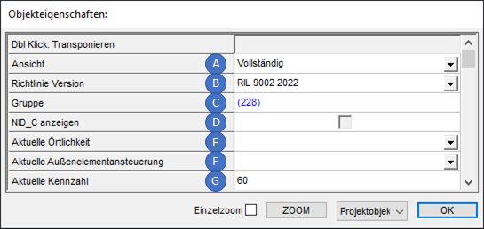
Bild: Objekteigenschaften des Projektobjektes
oÜber das Dropdown 'Ansicht' (A) wird die Sichtbarkeit von Objekteigenschaften für Dialoge festgelegt. Folgende Ansichten können eingestellt werden:
Wert der Eigenschaft |
Beschreibung |
Standard |
Empfohlene Standardansicht, Voreinstellung für neue Projekte. |
Reduziert |
Reduzierte Ansicht, nur Darstellung der wesentlichen Eigenschaften, z.B. empfohlen für die Planung von Signalen, siehe hierzu auch Signale EPU. |
ETCS L2 |
Spezielle Ansicht für die Planung von ETCS Level 2 Projekten. Die Eigenschaften von Signalen werden in der Reihenfolge der ETCS-Muka Signaltabelle angezeigt. Für die ETCS-Fachplanung nicht relevante Eigenschaften werden nicht dargestellt. |
ZBS |
Spezielle Ansicht für die Planung von ZBS-Projekten (Zugsicherung Berliner S-Bahn), Darstellung der ZBS-Eigenschaften. Für die ZBS-Planung nicht relevante Eigenschaften werden nicht dargestellt. |
Vollständig |
Vollständige Darstellung aller Objekteigenschaften. |
oÜber das Dropdown 'Richtlinie Version' (B) kann für Objekte die Darstellung der Eigenschaften gemäß der eingestellten Richtlinie realisiert werden. Zurzeit werden die Versionen 'RIL 9002 2017', 'RIL 9002 2022' und 'RIL 9002A01 2022 Digital' angeboten.
oÜber die Eigenschaft 'Gruppe' (C) sind die LST-Planungsgruppen mit dem Projektobjekt verlinkt. Informationen zu den LST-Planungsgruppen sind unter Erstellen und Bearbeiten von LST-Planungsgruppen zu finden. LST-Planungsgruppen werden für den Export der Objektarten der verschiedenen Untergewerke benötigt, siehe hierzu auch PlanPro Export, Schritt 4.
▪Standardwert ist die LST-Planungsgruppe mit der Untergewerkart 'ESTW'. Diese wird beim Anlegen des Projektes automatisch erzeugt.
oDie Checkbox 'NID_C anzeigen' (D) legt bei der Planung von ETCS Level 2 Projekten oder bei der Planung von ZBS-Projekten für Datenpunktbezeichnungen die Sichtbarkeit des Präfix der jeweiligen Datenpunktadresse bzw. der Gebietskennung NID_C in der Zeichnung fest.
Wert der Checkbox |
Bedeutung |
Beschreibung |
|
Wert 'Ja' |
Die Datenpunktbezeichnungen werden inklusive Gebietskennung NID_C in der Zeichnung angezeigt. |
|
Wert 'Nein' |
Die Datenpunktbezeichnungen werden entsprechend der Eigenschaft 'Kurzbezeichnung' (DP-Adresse ergänzt durch Anwendungskennung, ohne NID_C) in der Zeichnung angezeigt. |
|
undefiniert |
wie Strich gesetzt (Standardwert)
|
oFür die Eigenschaften 'Aktuelle Örtlichkeit' (E) und 'Aktuelle Außenelementansteuerung' (F) wird die Vorbelegung zu einem späteren Zeitpunkt im Planungsprozess vorgenommen, siehe auch Festlegen der Projekteigenschaften und Vorbelegungen.
oFür die Eigenschaft 'Aktuelle Kennzahl' (G) kann die eindeutige Kennzahl der Sicherungstechnik bzw. operativen Leittechnik des Bedienbezirks für die aktuelle Betriebsstelle angegeben werden. Alternativ kann auch ein Kennzahlbereich angelegt werden. Enthält die Betriebsstelle mehrere Kennzahlen, können für die zugehörigen Topologischen Kanten Kennzahlbereiche festgelegt werden, um den entsprechenden Vorgabewert zur Kennzahl für die Eigenschaften neu eingefügter LST-Objekte zu gewährleisten. Hierzu siehe auch Festlegen von Kennzahlbereichen.
Die Eigenschaft des Kennzahlbereiches wird primär verwendet, die Eigenschaft im Projektobjekt sekundär, d.h. nur dann wenn für den Bereich, in dem sich das LST-Objekt befindet, kein Kennzahlbereich definiert wurde.
▪Die Kennzahl kennzeichnet eine Betriebsstelle oder einen Betriebsstellenteil. Sie darf nicht mit der Bahnhofsnummer der Zugnummernmeldeanlage (Ril 819.0731) verwechselt werden. Sie wird in den Elementnamen der LST-Objekte verwendet.
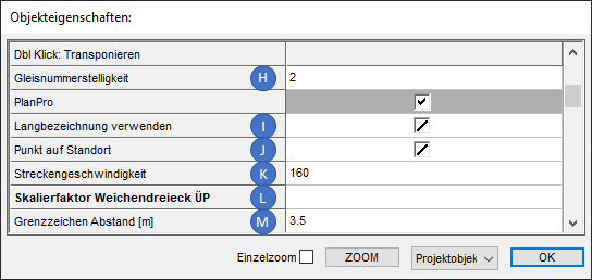
Bild: Objekteigenschaften des Projektobjektes
oÜber die Eigenschaft 'Gleisnummerstelligkeit' (H) ist die Stelligkeit der Gleisnummer für die Betriebsstelle im Lageplan zu vermerken. Gleisnummern können hierbei zweistellig oder dreistellig sein.
▪Die Belegung der Eigenschaft hat z. B. Einfluss auf die Bezeichnung bzw. auf die Eigenschaft 'Örtlicher Elementbezeicher' von Freimeldeabschnitten und steuert hier die Darstellung führender Nullen der Gleisnummern.
oDie Checkbox 'Langbezeichnung verwenden' (I) hat Einfluss auf die Darstellung der Bezeichnungen der LST-Objekte in der Projektzeichnung:
Wert der Checkbox |
Bedeutung |
Beschreibung |
|
Wert 'Ja' |
Die Bezeichnungen werden entsprechend der Eigenschaft 'Bezeichnung Lageplan Lang' ausgegeben. |
|
Wert 'Nein' |
Die Bezeichnungen werden entsprechend der Eigenschaft 'Bezeichnung Lageplan Kurz' ausgegeben. |
|
undefiniert |
wie Strich gesetzt (Standardwert) |
▪Über das Bereichsobjekt Kennzahlbereich kann für Bereiche der Topologie festgelegt werden, ob die Langbezeichnung für die Darstellung der Objekte verwendet werden soll oder nicht. Die Eigenschaft des Kennzahlbereiches wird primär verwendet. Die Eigenschaft 'Langbezeichnung verwenden' (E) im Projektobjekt wird sekundär verwendet, d.h. nur dann wenn für den Bereich, in dem sich das LST-Objekt befindet, kein Kennzahlbereich definiert wurde.
oÜber die Checkbox 'Punkt auf Standort' (J) kann festgelegt werden, wie beim Einfügen von Objekten die zugrundeliegende Strecke für die Berechnung des Standorts ermittelt wird.
Wert der Checkbox |
Bedeutung |
Beschreibung |
|
Wert 'Ja' |
Das zugrundeliegende Bereichsobjekt 'Strecke' ist vor der Positionierung eines einzufügenden Objekts in der Zeichnung zu wählen. Während des Einfügeprozesses erfolgt dann zunächst die Streckenwahl, anschließend ist die Kilometerangabe vorzunehmen. Sind mehrere topologische Kanten dem Streckenobjekt zugeordnet und liegen diese Kante im angegebenen Kilometerbereich, werden mehrere mögliche Einfügepositionen gefunden und temporär auf der Topologie markiert. Durch Auswahl eines markierten Einfügepunktes wird die Positionierung des einzufügenden Objekts vorgenommen. |
|
Wert 'Nein' |
Die Festlegung der zugrundeliegenden Strecke erfolgt global über die 'Funktion 'Strecke aktuell setzen'. Anschließend kann z.B. über die Funktion 'Punkt auf Standort' eine Kilometerangabe vorgenommen und ein Punkt entlang der aktuellen Strecke gesetzt werden. Die Positionierung von Objekten erfolgt beim Einfügeprozess anschließend durch Punktwahl. |
|
undefiniert |
wie Strich gesetzt (Standardwert) |
oÜber die Eigenschaft 'Streckengeschwindigkeit' (K) kann der Grundwert für die Streckengeschwindigkeit festgelegt werden. Dieser Wert wird für Haupt-, Vor- und Sperrsignale als Basis für die automatische Berechnung der Soll- und Mindestsichtbarkeiten bezüglich der zugehörigen Richlinien 819.0202, 819.0203 oder 819.0302 verwendet. Die Besonderheiten bei Verkürzung der Entfernung von 500Hz Magneten sind ggf. manuell zu berücksichtigen. Standardwert ist 160.
oÜber die Eigenschaft 'Skalierfaktor Weichendreieck ÜP' (L) kann die Größe der Weichendreiecke (Weichenelemente) für die Darstellung in schematischen Plänen angepasst werden.
oÜber die Eigenschaft 'Grenzzeichen Abstand [m]' (M) kann für das Einfügen von Grenzzeichen festgelegt werden, welcher Gleisabstand der Weichenschenkel (in Metern) für das automatische Positionieren von Grenzzeichen verwendet wird. Standardmäßig ist der Wert auf '3.5' Meter festgelegt.
▪Für alle Grenzzeichen, die nach Anpassung des Wertes eingefügt werden, wird der neue Wert als Vorgabewert für die Positionierung verwendet.
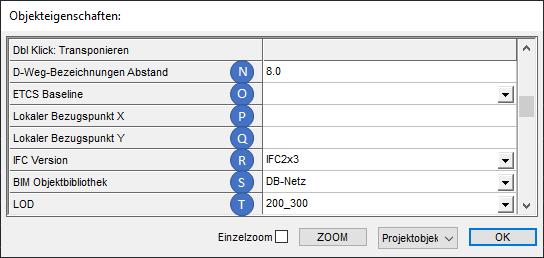
Bild: Objekteigenschaften des Projektobjektes
oÜber die Eigenschaft 'D-Weg Bezeichnungen Abstand' (N) kann für das Erstellen der D-Wege festgelegt werden, in welchem Abstand die Abstandsangaben der D-Wege am Ziel des D-Weges automatisch positioniert werden sollen. Standardwert sind '8.0' Zeicheneinheiten.
▪Für alle D-Wege, die nach Anpassung des Wertes eingefügt werden, wird der neue Wert als Vorgabewert für die Positionierung der Abstandsangabe verwendet.
oDie Einstellung über das Dropdown 'ETCS Baseline' (O) bestimmt für die Planung von ETCS Level 2 Projekten die zugrundeliegende Baseline, nach der projektiert werden soll, siehe auch Automatisches Ermitteln von Korrekturpunkten.
oDie Eigenschaften 'Lokaler Bezugspunkt X' (P) und 'Lokaler Bezugspunkt Y' (Q) können beim IFC-Export für ein 3D-Darstellungstool zur Bereinigung der X- und Y-Koordinaten verwendet werden.
oÜber das Dropdown 'IFC Version' (R) kann die Version für den IFC-Export eingestellt werden. Zurzeit werden die Versionen 'IFC2x3' und 'IFC4' unterstützt. Standardwert ist 'IFC2x3'.
oÜber das Dropdown 'BIM Objektbibliothek' (S) kann die BIM Objektbibliothek ausgewählt werden. Zurzeit stehen die Bibliotheken 'DB Netz' oder 'ProSig' zur Verfügung. Die zugehörigen Vorlagen werden mit der Version mitgeliefert. Standardwert ist 'DB-Netz'.
oÜber das Dropdown 'LOD' (T) kann der Detaillierungsgrad für den IFC-Export bestimmt werden. Mögliche Werte sind '050', '100', '200_300' oder '400_500'. Standardwert ist '200_300'.
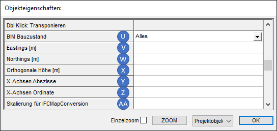
Bild: Objekteigenschaften des Projektobjektes
oÜber das Dropdown 'BIM Bauzustand' (U) kann bestimmt werden, welche Objekte des aktuellen Bauzustands in die IFC-Datei exportiert werden. Mögliche Werte sind 'Alles', 'Bestand', 'Einbau' und 'Ausbau'. Bestand umfasst sowohl die Bestandsobjekte als auch die Einbauobjekte des aktuellen Bauzustands. Standardwert ist 'Alles'.
oFür die Eigenschaften 'Eastings [m]' (V), 'Northings [m]' (W), 'Orthogonale Höhe [m]' (X), 'X-Achsen Abszisse' (Y), 'X-Achsen Ordinale' (Z) und 'Skalierung für IFCMapConversion' (AA) sind für den IFC-Export ab Version IFC4 die Werte entsprechend anzugeben, wenn eine spezielle Transformation in ein Geo-Referenzsystem vorgenommen werden soll. Zusätzlich ist in mindestens einem Geo-Punkt das gewünschte Koordinatensystem einzutragen. Für IFC2x3 werden diese Angaben nicht berücksichtigt.
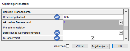
Bild: Objekteigenschaften des Projektobjektes
oÜber die Eigenschaft 'Bremswegabstand' (AB) kann die Länge des Bremsweges der zugrundeliegenden Strecken bestimmt werden.
oDie Eigenschaft 'Darstellungs-Koordinatensystem' (AC) kann im Fall von zugrundeliegenden Kilometrierungsdaten mit mehreren Koordinatensystemen aus einer importieren GND-Datei angegeben werden. Für den Import siehe auch Importieren der Kilometrierung, Weichen und Neigung aus GND.
oFür die Checkbox 'S-Bahn Projekt' (AD) kann der Haken gesetzt werden, wenn das aktuelle Projekt für den Bereich der Berliner S-Bahn geplant wird, siehe auch Planung von ZBS-Projekten.
Wert der Checkbox |
Bedeutung |
Beschreibung |
|
Wert 'Ja' |
Beim automatischen Ermitteln der Bezeichnungen der Freimeldeabschnitte wird nicht die Zahl hochgezählt, sondern Buchstaben angehängt und hochgezählt. Hierbei wird der Buchstabe 'J' ausgelassen. Die Zahl für den Abschnitt in der Bezeichnung kann vom Anwender bei Bedarf geändert werden. |
|
Wert 'Nein' |
Beim automatischen Ermitteln der Freimeldeabschnittsbezeichnungen wird die Zahl hochgezählt. |
|
undefiniert |
wie Strich gesetzt (Standardwert) |
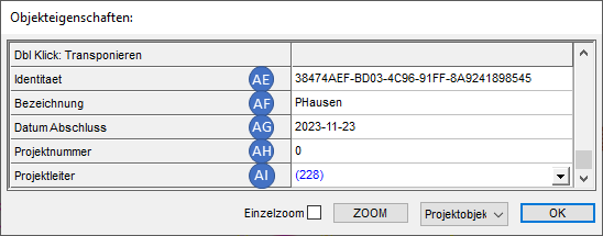
Bild: Objekteigenschaften des Projektobjektes
oDie Angabe der Eigenschaft 'Identität' (AE) ist die eindeutige Identifizierung des Objektes mit Hilfe der GUID. Bei Verlinkungen auf ein Objekt wird eine entsprechende Referenz angegeben. Verlinkungsattribute setzen sich aus dem Präfix 'ID_' und in der Regel dem entsprechenden Objektnamen zusammen ('ID_[Objekt]'). Die Eindeutigkeit der Verlinkung ergibt sich aus der Spezifikation der GUID, siehe hierzu RFC 4122 http://tools.ietf.org/html/rfc4122
oFür die Eigenschaft 'Bezeichnung' (AF) ist die 'Gekürzte Langbezeichnung' einer Baumaßnahme anzugeben, die über mehrere Planungsgruppen realisiert wird. z. B. Grunderneuerung Strecke xxxx.
DB-Regelwerk: Bisher keine eindeutige Abbildung.
Meist Zusatzeintrag auf Planungsunterlagen außerhalb des Standard-Schriftfelds nach Ril 886.0102.
Standardwert ist 'Projektname'.
oFür die Eigenschaft 'Datum Abschluss' (AG) ist das Datum des Abschlusses des Planungsprojektes anzugeben. Bis zum tatsächlichen Abschluss handelt es sich dabei um ein geplantes Datum, das iterativ nachzupflegen ist. DB-Regelwerk: Bisher ohne eindeutige Abbildung.
oFür die Eigenschaft 'Projektnummer' (AH) ist die Angabe der Projektnummer vorzunehmen. Die Struktur wird im LST-Datenmodell nicht vorgegeben.
DB-Regelwerk: Bisher keine eindeutige Abbildung.
oFür die Eigenschaft 'Projektleiter' (AI) ist der Projektleiter anzugeben, der für die erfolgreiche Projektabwicklung verantwortlich ist. Die Eigenschaft enthält einen Link zum zugehörigen Objekt 'Akteur'.
DB-Regelwerk: Bisher ohne eindeutige Abbildung.
▪Standardwert ist das Objekt 'Akteur', das beim Anlegen des Projektes automatisch erzeugt wurde. Zum Ändern der Eigenschaften des Akteurs ist die Projekteigenschaft 'Projektleiter' (AI) zu markieren und über Rechtsklick das Kontextmenü aufzuschalten. Über den Kontextmenüpunkt 'Referenzobjekt anzeigen' (AJ) werden die Eigenschaften des verknüpften Objekts 'Akteur' angezeigt und können bearbeitet werden. Zum Anlegen weiterer Akteure und zum Bearbeiten der Eigenschaften von Akteuren siehe auch Erstellen und Bearbeiten von Akteuren und Akteurzuordnungen.
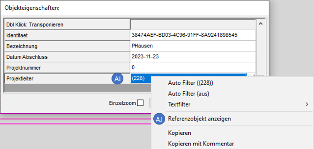
Bild: Aufschalten der Eigenschaften des automatisch zugeordneten Akteurs über das Kontextmenü
oZusätzlich gibt es weitere Eigenschaften, die für alle Objekte gültig sind, siehe hierzu Beschreibung der allgemeinen Objekteigenschaften.
