Processing of Construction Stages

Contents
Process:
•Creating and displaying of Construction Stages
Requirements:
Description:
The Conversion from older techniques to the CBI technique is usually planned in several construction phases. In a construction phase, the elements are represented in the plan as follows:
oElements to be installed are displayed in the color Red.
oElements to be dismantled are displayed in the color Yellow.
oElements of the Current Inventory are displayed in their inventory color, which is defined by the corresponding layer.
oDismantled Elements are displayed in the color Dark red.
oArea Objects are usually not displayed in the installation color during insertion, but they are displayed in the removal color during removal. For example: after a reorientation, the area objects have to be re-located at the installed edges, so that the previous position of the area objects is easier to recognize.
The Editing of the PSO for construction stages is possible via the group 'Construction Stages - EPU' in the ribbon 'ProSig EPU'. For the representation of objects in a certain construction stage, it is necessary to ensure first that the construction stage exists in the project. After setting the Construction stage, the existing Object data can be edited for this construction stage depending on the required representation.
Procedure:
1.In the Setting up Planning Project, construction stages 0 and 1 are generated automatically. The construction stages can be viewed and switched via the ribbon.
Ribbon: ProSig EPU -> Construction Stages - EPU -> Setting the Processing frame
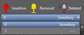
Illus.: The 'Setting the Processing frame' drop-down list is opened, after creating the project.
oConstruction stage 0 is used to define and update the inventory data.
In this construction stage, customization's can be made in the drawing without being interpreted by the program as construction stage changes.
oConstruction stage 1 is used as the default for editing the project with construction stages.
In construction stage 1, like all other construction stages, the inserting or updating of elements is represented as installed. When elements are deleted, they are displayed as dismantled.
oBy setting the processing frame to a specific construction stage via the drop-down list, the PSO's are displayed accordingly in the drawing.
2.To Define further construction stages or to edit existing construction stages, it is possible to call the Bauzustandseditor via the arrow at the bottom right of the group 'Construction Stages - EPU'.
Ribbon: ProSig EPU -> Construction Stages - EPU -> Arrow at the bottom right margin
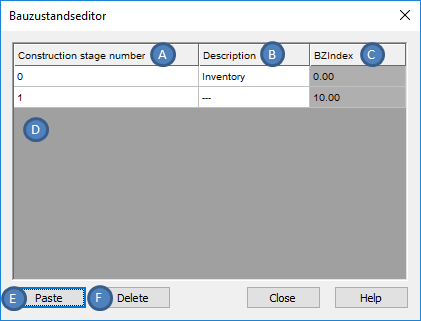
Illus.: Bauzustandseditor
oThe Construction stages 0 and 1 are automatically created with their Construction stage number (A) as soon as the project is created. The Construction stage number is displayed in the ribbon 'Setting the Processing frame' drop-down list.
oThe Assignment of the attribute 'Description' (B) is optional. The description will be displayed in the drop-down list 'Setting the Processing frame'.
oThe Attribute 'BZIndex' (C) is automatically assigned during the creation of a construction stage. The BZIndex is used as the basis for sorting the construction stages and determines the display of the construction stages in the 'Set the Processing frame' drop-down list.
3.To Define a new construction stage for the project, first select a construction stage in the construction stage editor. Subsequently a new construction stage can be inserted by clicking the button 'Paste' (E) behind the marked construction stage. For the newly created construction stage, at least the information of the Construction stage number (A) should be entered in order to simplify the later selection in the drop-down list 'Set the Processing frame'
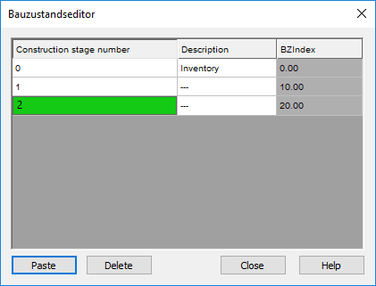
Illus.: Creating a new Construction Stage with the Bauzustandseditor
oAfter closing the dialog, the construction stages are sorted according to their BZIndex and displayed in the drop-down list 'Setting the Processing frame' or when the construction stage editor is switched on again.
4.The Button 'Delete' (F) can be used to delete an existing construction stage. Objects that have been modified in the deleted construction stage must be re-examined in the subsequent construction stages.
5.In order to edit the data of a PSO for a certain construction stage, the processing frame has to be set to the desired construction stage via the drop-down list 'Setting the Processing frame'. Subsequently, the changes relevant for this construction stage can be executed at the PSO. The Changes are displayed directly in the drawing. Some examples are given in the following table.
Ribbon: ProSig EPU -> Construction Stages - EPU -> Setting the Processing frame
Illus.: Set processing frame to edit PSO for Construction Stages
Nr.
|
Construction stage for |
Implementation |
Result in the drawing |
Example |
|---|---|---|---|---|
1 |
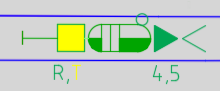
Removal PSO
|
Apply the AutoCAD function 'DELETE' to the Object. |
The Object is displayed in the Recovered color. |
 |
2 |
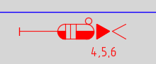
Insertion PSO |
Use the relevant function to insert the object, see Planning Processes. |
The Object is displayed in the new work color. |
 |
3 |
Removal of a PSO at the old location and insertion of this PSO at a new location |
Move object (using the Object grips, the AutoCAD 'MOVE' function or the function 'Move Objects Along Topology' (SAK)). The location input is automatically updated. |
The Object is displayed at the old location in the recovered color, at the new location in the new work color. |
 |
4 |
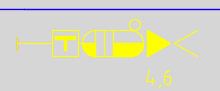
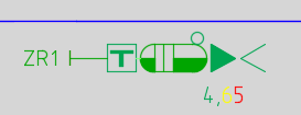
Changing a Visible attribute (for example, Name) |
1.Apply the functions 'Edit Object' (DBATTE) or 'Edit Object(s)' (OE) to the corresponding object (PSO). 2.Adjust the attribute. |
The old attribute value is displayed in the recovered color, the new attribute value is displayed in the new work color. |
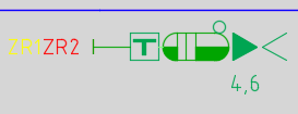 |
5 |
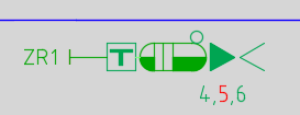
Changing the Display concept for a Signal (PSO) |
3.Apply the function 'Edit Object' (DBATTE) or 'Signals - EPU' (PRS_SIGNAL) to the corresponding Signal (PSO). 4.Adjust the attribute 'Signal symbol' to the required Signal aspect. |
The old attribute value is displayed in the recovered color, the new attribute value is displayed in the new work color. |
 |
Adding a Display concepts to the Signal (PSO) |
5.Apply the function 'Edit Object' (DBATTE) or 'Signals -EPU' (PRS_SIGNAL) to the corresponding Signal (PSO). 2.In the section 'Signal Frame', select the frame with the Frame type 'Zusatzanzeiger'. 3.In the section 'Signal Aspect' use the button 'New' to add a new Signal aspect. 4.For the new Signal aspect set the Object attribute 'Signal aspect ID' accordingly. 5.Check the Object attribute 'Switched' for the new Signal aspect. 6.Adjust the attribute 'Signal symbol' for the new Signal aspect. |
The new Display concept is displayed in the new work color. |
 |
|
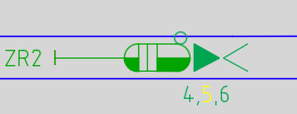
Removing a Display concepts from the Signal (PSO) |
6.Apply the function 'Edit Object' (DBATTE) or 'Signals - EPU' (PRS_SIGNAL) to the corresponding Signal (PSO). 7.In the section 'Signal Frame', mark the corresponding frame with the Frame type 'Zusatzanzeiger'. 3.In the section 'Signal Aspect' use the button 'Delete' to remove the Signal aspect. 4.If necessary, an empty frame can be deleted in the section 'Signal Frame' with the button 'Delete'. |
The remote Display Concept is displayed in the recovered color. |
 |
|
8 |
Change of the Display concept of an Auxiliary Indicator from Switchable to Metal board |
7.Apply the function 'Edit Object' (DBATTE) or 'Signals - EPU' (PRS_SIGNAL) to the corresponding Signal (PSO). 8.Set the attribute 'Switched' to '/' for the required Signal aspect. 9.There may be only one signal aspect for a non-switched auxiliary indicator. If there is more Signal aspect, these should be deleted, see also Nr. 7. |
The filled inner surface of the Auxiliary indicator is displayed in the recovered color. |
 |
9 |
Change of the Display concept of an Auxiliary Indicator from Metal board to Switchable |
10.Apply the function 'Edit Object' (DBATTE) or 'Signals - EPU' (PRS_SIGNAL) to the corresponding Signal (PSO). 11.Tick the attribute 'Switched' for the required Signal aspect. 12.Subsequently, further switchable signal aspects can be added to this Auxiliary indicator, see also Nr. 6. |
The filled inner surface of the Additional indicator is displayed in the new work color. |
 |
10 |
Changing an Auxiliary Indicators on the Signal (PSO) |
13.Apply the function 'Edit Object' (DBATTE) or 'Signals - EPU' (PRS_SIGNAL) to the corresponding Signal (PSO). 14.In the section 'Signal Aspect' adjust the attribute 'Signal aspect ID' for the signal aspect to be changed. |
The old Auxiliary Indicator is displayed in the recovered color, the new Auxiliary Indicator is displayed in the new work color. |
 |
11 |
Inserting a new Auxiliary Indicator at the Signal (PSO) |
15.Apply the function 'Edit Object' (DBATTE) or 'Signals - EPU' (PRS_SIGNAL) to the corresponding Signal (PSO). 16.In the section 'Signal Frame' with the button 'New' create a new frame and define the attribute 'Frame type' accordingly. 17.Mark the newly created Signal Frame.
18.In the section 'Signal Aspect' use the button 'New' to add a new Signal aspect to this frame. 19.Assign the attribute 'Signal aspect ID' to the new Signal aspect and if necessary edit the associated attributes. |
The new Auxiliary indicator is displayed in the new work color. |
 |
12 |
Deleting an Auxiliary Indicator for a Signal (PSO) |
20.Apply the function 'Edit Object' (DBATTE) or 'Signals - EPU' (PRS_SIGNAL) to the corresponding Signal (PSO). 21.In the section 'Signal Aspect' mark the signal aspects to be deleted and press the button 'Delete'. Subsequently, the empty frame can be removed in the section 'Signal Frame' with the button 'Delete'. |
The new Auxiliary indicator is displayed in the recovered color. |
 |
13 |
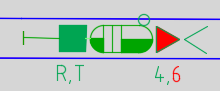
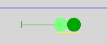
Removal of the Signal aspect Hp_1 at the Signal (PSO) Signal System Hv |
22.Apply the function 'Edit Object' (DBATTE) or 'Signals - EPU' (PRS_SIGNAL) to the corresponding Signal (PSO). 23.In the section 'Signal Aspect' mark the signal aspect 'Hp_1' to be deleted and press the button 'Delete'. |
The Line is displayed at the Signal in the new work color. |
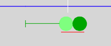 |
14 |
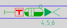
Insertion of the Signal aspect Hp_1 at the Signal (PSO) Signal System Hv |
24.Apply the function 'Edit Object' (DBATTE) or 'Signals - EPU' (PRS_SIGNAL) to the corresponding Signal (PSO). 25.In the section 'Signal Frame' mark the frame with the 'Frame type 'Schirm'. 26.In the section 'Signal aspect' use the button 'New' to add a new Signal aspect to this frame.
27.Set the ID 'Hp_1' for the attribute 'Signal aspect ID' in the newly created Signal aspect. |
The Line is displayed at the Signal in the recovered color. |
 |
15 |
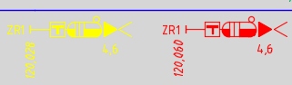
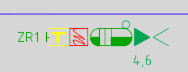
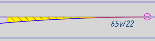
Modification of the type of controlling for switches (PSO) using the example of conversion of the remotely controlled electrically operated point to a locally controlled electrically operated point |
28.Apply the function 'Edit Object' (DBATTE) to the Switch Element (PSO) of the Switch to be adapted. 29.Adjust the attribute 'Type of controlling' accordingly. |
Insertion are displayed in the new work color, Removal in the recovered color. |
 |
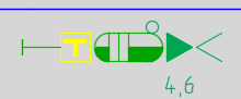
16 |
Changing the Type of Sensor (PSO) |
30.Apply the function 'Edit Object' (DBATTE) for the Sensor (PSO) to be adapted. 31.Adjust attribute 'Type' accordingly. |
Insertion are displayed in the new work color, Removal in the recovered color. |
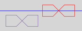 |
Table: Customizing Examples for editing PSO for Construction Stages
6.Im Folgenden wird die Auswirkung beim Editieren der Eigenschaften eines PSO auf andere Bauzustände anhand des Beispiels der Signalbezeichnung bzw. der Eigenschaft 'Örtlicher Elementbezeichner' erläutert.
1.Zunächst wird ein Signal mit der Bezeichnung 'A' (schwarz) im Bestand eingefügt. Alle weiteren Bauzustände übernehmen diesen Wert (hier beispielhaft grau dargestellt).
Bauzustand |
Bestand bzw. 0 |
1 |
2 |
3 |
4 |
Örtlicher Elementbezeichner |
A |
A |
A |
A |
A |
2.Anschließend wird in Bauzustand 3 die Bezeichnung auf den Wert 'B' geändert (gelb/rot) und entsprechend in die nachfolgenden Bauzustände mit dem Wert 'B' übernommen.
Bauzustand |
Bestand bzw. 0 |
1 |
2 |
3 |
4 |
Örtlicher Elementbezeichner |
A |
A |
A |
AB |
B |
3.In Bauzustand 1 wird die Bezeichnung auf den Wert 'C' geändert (gelb/rot), was sich auf Bauzustand 2 (grau) auswirkt und die Änderung in Bauzustand 3 ebenfalls beeinflusst.
Bauzustand |
Bestand bzw. 0 |
1 |
2 |
3 |
4 |
Örtlicher Elementbezeichner |
A |
AC |
C |
CB |
B |
7.Mit der Funktion 'Objekt editieren Bauzustand' können die Änderungen eines in der Zeichnung ausgewählten Objektes über alle Bauzustände hinweg angezeigt und bearbeitet werden. Außerdem kann das Vorhandensein eines Objektes in einem Bauzustand festgelegt werden.
Befehlszeile: PRS_BZ_ANZEIGE
Multifunktionsleiste: ProSig EPU -> Bauzustände - EPU -> Objekt editieren Bauzustand

Bild: Eigenschaften des Signals am Beispiel aus Schritt 6 (Anpassung des Örtlichen Elementbezeichners)
8.Über die Eigenschaft 'Bauzustand vorhanden' kann das Vorhandensein von Objekten in Bauzuständen festgelegt werden.

Bild: Eigenschaften des Signals aus dem Beispiel aus Schritt 6 (Ausbau in Bauzustand 2 und Wiedereinbau in Bauzustand 4)
oWird die Checkbox 'Bauzustand vorhanden' gesetzt mit 'Ja', ist das Objekt im entsprechenden Bauzustand vorhanden oder eingebaut.
oWird die Checkbox 'Bauzustand vorhanden' gesetzt mit 'Nein', ist das Objekt im entsprechenden Bauzustand nicht vorhanden oder ausgebaut.
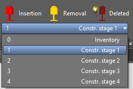
9.Using the buttons 'Insertion', 'Removal' and 'Deleted' in the ProSig ribbon, it is possible to display or hide installed, dismantled or deleted objects (which were removed in the previous construction stage).
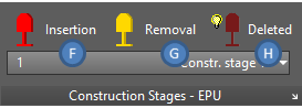
Illus.: Buttons for the representation of the Construction Stage Objects
oDepending on the current representation, the objects to be installed can be displayed or hidden in the drawing using the button 'Insertion' (F).
When the screen of the signal on the button is filled in, the objects to be installed are displayed.
When the screen of the signal on the button is hollow, the objects to be installed are hidden.
Ribbon: ProSig EPU -> Construction Stages - EPU -> Insertion
oDepending on the current representation, the objects to be dismantled can be displayed or hidden in the drawing using the button 'Removal' (G).
When the screen of the signal on the button is filled in, the objects to be dismantled are displayed.
When the screen of the signal on the button is hollow, the objects to be dismantled are hidden.
Ribbon: ProSig EPU -> Construction Stages - EPU -> Removal
oDepending on the current representation, the objects to be displayed as deleted in the current construction stage can be displayed or hidden in the drawing with the button 'Deleted' (H).
When the screen of the signal on the button is filled in, the deleted objects are displayed.
When the screen of the signal on the button is hollow, the deleted objects are hidden.
Ribbon: ProSig EPU -> Construction Stages - EPU -> Deleted
10.User-defined color adjustments for installed, dismantled and deleted elements can be implemented. Please contact ProSig Support.
11.To Represent the final state in a project, a further construction stage is defined and set. No changes are permitted in this last construction stage.