Signals - EPU

Contents
Process:
•Insertion of Real Signals
•Processing of Signal Attributes
•Create and Edit Signal Aspects
Requirements:
see Planning Signals
Description:
Signals are dot-like PSO located at the topological edge.
In ProSig, the signal of the field installation consists of
•one or more Signal mountings, their attributes determines the construction of the signal (e.g. 'Fundament', 'Signalanordnung'). The respective constructive characteristics are substantiated by the assigned Standard drawing. For special constructions, the standard drawing is replaced by an approval document, which is attached via a comments section. A Signal mount can also accommodate other Signal mounts (e.g. for Signal gantries assignment of a working platform to a Signal bracket).
•one or more Signal frames assigned to a Signal Mounting. For a Signal frame, signal aspects are assigned that form a group or that implement a construction (e.g. three Signal frames and two Auxiliary indicators are needed to construct the screen). The assignment of all signal frames to a signal represents the logical combination of all signal aspects which belong to a signal. The assignment of a signal frame to a signal mount represents the structural construction of the signal.
•one or more Signal aspects displayed simultaneously and forming a common logical context. This optical information provides the driver with the current handling instructions. The Signal aspects are described in the Signalling regulation and rule book (Ril 301). A separate instance has to be created for each signal aspect.
If Signal silhouette are assigned to a common point, but they do not require a common logical interpretation, they are assigned to different signals.
If a signal can display several signal silhouettes, these are to be grouped together in the same way as for construction, whereby each of these groups forms a Signal Frame.
By changing the attributes of a signal (e.g. changing the attribute 'Bedienart') or by adapting the allocated signal aspects, the view of the signal in the project drawing is updated accordingly.
Concrete examples for generating different Signal types are given below:
Example: Inserting a Multi-Section Shunting Signals
Example: Inserting a Stand-Alone Subsidiary Signals
Example: Inserting a Shunting Signal at a Dwarf Mast
Example: Inserting at the Signal Brackets
Example: Inserting Speed Restriction Boards
Example: Inserting a Distant Signal Repeaters
When representing construction stages for signals, the construction stage logic is also displayed for individual signal aspects.
In the PlanPro glossary, the structure of the signal is formulated as follows:
Signal Aspect (Signal_Signalbegriff)
This is a visual representation of information that is intended to transmit the signal to the driver.
Signal aspects are described in the Signalling regulation and rule book (Ril 301) by a short designation (e.g. 'Zs 1') and/or by a long designation (e.g. 'substitute signal'). Both these and other fixed attributes such as the set of values of the displayed symbols of a signal aspect are defined in the object Signal aspect, which is integrated by means of the attribute 'Signal aspect ID'.
Activation time, Lighting and Switching are not fixed, but can be connected to the signal aspect according to Signalling regulation and rule book and consequently the attribute of the signal aspect.
A Signal aspect is always located in a signal frame.
Signal Silhouette
Comprises of all the forms, colors, light duration and other visible characteristics (e.g. symbols, letters, numbers) defined for a visible signal aspect. Signal tones (audible signs) are not Signal silhouette.
If a signal silhouette can be changed depending on the operational state, it is called as switchable, otherwise as fixed (see Signal frame).
Signal Frame (Signal_Rahmen)
•Assignment of one or more Signal aspects to a constructive element (Signal mounting) as well as
•Assignment of Signal aspects of a subordinate signal to another signal without reference to the track route.
Fictitious signals will not have a Signal frame as they cannot display a signal aspect.
One or more Signal frames form a signal. The grouping of signal aspects within a signal to form signal frames is performed by means of the constructive design, e.g. all signal aspects of the main signal target or all signal aspects of an auxiliary indicator are combined to form a Signal frame.
If the number or type of signal aspects of a signal frame is changed as a function of its operational state, it is referred to as switchable, otherwise as fixed. In the SCT data model, this attribute is defined as an attribute of the signal aspects; a signal frame can be switched precisely when at least one of the included signal aspects is switchable.
•Typical switchable signal frames are the signal target of a Multi-section shunting signal, the light signal of an auxiliary indicator and the form or light signal of a switch signal.
•Typical fixed signal frames are the signal type indicator of a main signal, the semaphore signal of an auxiliary indicator and the stop board.
As planned, the signal frame is used to assign signal aspects of a subordinate signal to another signal without reference to the track route.
Signal Mounting (Signal_Befestigung)
Construction element that is used to structurally accommodate one or more signal frames.
The concrete constructive characteristics are included in a standard drawing which is represented by a GUID reference. For special designs, the standard drawing is replaced by the corresponding approval documents. These documents should be attached with a comment.
Signal mounts can also accommodate other signal mounts (e.g. a bracket carries a working platform). At least one object signal frame or signal mounting is assigned to a signal mounting.
The Mounting type is the description of the signal mounting in order to determine the basic type without a Standard drawing. If the option 'Sonstige' is selected, a comment with corresponding explanations needs to be added.
As a rule, the following Mounting types are specified for the Signal mounting:
•'Signalanordnung Mast' for Stationary signals
•Foundations for 'Signalanordnung Mast'
•'Signalanordnung Arbeitsbühne' for Signals at Signal brackets or Signal gantries
•'Signalausleger' or 'Signalbrücke' respectively
•'Signalanordnung Sonstige' for Tunnel Signals
For special constructions, the standards 'Rahmen' (for all elements containing signal aspects) and 'Mast' (for all post-like support elements) are also available, but they are also assigned to a Default-Standard drawing. Further Signal mountings should be marked as 'Sonstige' and provided with a special design drawing instead of the standard drawing.
DB Rules and Regulations: Standard Drawings
(Source: PlanPro Glossary)
Procedure:
1.The Function 'Signal - EPU' is used to insert new signals or to display the attributes of existing signals.
Command Line: PRS_SIGNAL
Ribbon: ProSig EPU -> Equipment SCT -> Signal EPU
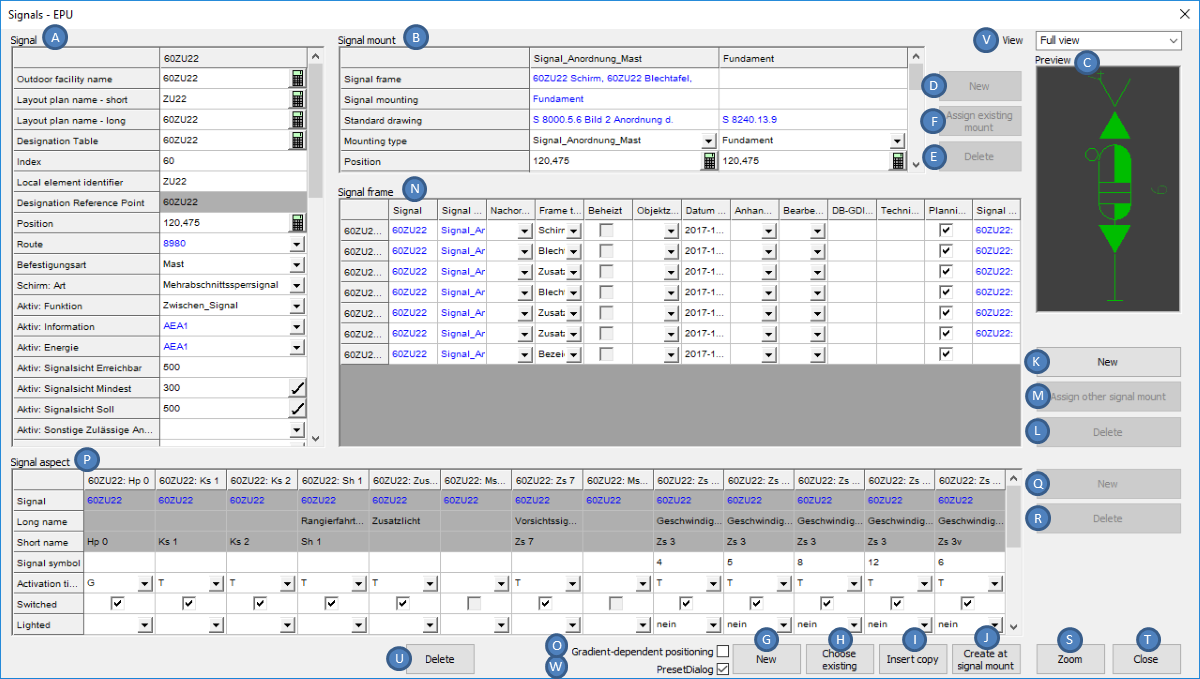
Illus.: Dialog for inserting signals (PSO) after the selection of a signal in the drawing
After invoking the function, the prompt 'Select signal:' is displayed on the command line. The following options are available in this case:
oTo display the attributes of an existing signal using the Signal Editor, select the corresponding object in the drawing. The Dialog is displayed with the attributes of the selected signal. The Signal is displayed in the Preview (C).
oTo Create a new signal, press the Enter key or click the right mouse button. The dialog opens empty.
2.When the dialog with the attributes of a signal is activated or the section 'Signal' (A) is marked, all signal aspects belonging to the signal are displayed in the section 'Signal aspect' (P). If a frame is marked in the section 'Signal frame' (N), only the signal aspects of the current frame are displayed in the section 'Signal aspect' (P).
3.With the option 'Gradient-dependent positioning' (O), the signals during the insertion (G, I) can become gradient-dependent positions. To perform a gradient-based location, gradient change points should be present in the project. As a rule, at the beginning of the planning process, they are provided by an XML Import or by the Import of Gradient data from GND. The manual creation of gradient change points is described under Creation of Gradient Data, Point 3. If there are no gradient change points in the project, the gradient 0 is used to calculate the gradient-based location. The insertion of a signal with gradient-dependent positioning is explained in more detail at Step 4.
4.With the button 'New' (G) a new signal is created.
oWith the option 'PresetDialog' (W) while inserting the signal a dialog is activated which allows the selection of a signal from a pre-selection of signal types.
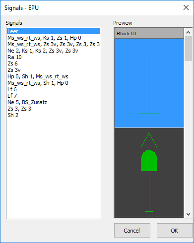
Illus.: Dialog for pre-selection of a Signal type to be inserted
Hints for insertion in the drawing are described on the page ProSig System Objects - Inserting Dot-like Objects.
When creating the Signal type 'Leer' a signal mount (Mounting type = 'Signalanordnung Mast') and an empty signal frame (Frame type = 'Schirm') are created.
If a special signal type is selected, specific attributes for this signal type are automatically assigned or corresponding signal aspects are automatically created.
In order to represent the instructions for the driver, signal aspects should be displayed on the frame, further information can be found at Point 5 and Point 12.
When inserting with Gradient-dependent positioning (O), the following points should also be edited:
1.'Select danger point' – A danger point is selected according to Ril. 819.0202, e.g.
oThe Fouling point marker of a Switch or Diamond crossover
oLimit of shunt indicator, Main signal, Shunting signal
oSwitch toe
oDerailer
oBuffer stop
oTrack closure
oLevel crossing
2.'Specify lateral position and working direction:' - Position and effective direction of the signal at the actual insertion point (after gradient-dependent positioning) have to be determined. The Procedure is described on the page ProSig System Objects - Inserting Dot-like Objects.
3.'Specify gradient-based distance (0m/50m/100m/200m) : <200.00>:' - Enter the base distance that forms the basis for the Overlap (default value 200m).
4.If necessary, 'Multiple target positions found. Target positions marked. Select target position:' – Multiple target positions are found. This is the case, if the possible track path branches through switches or crossings. The desired target position of the signal should be selected.
5.'Select point not to be used for the calculation of the governing gradient:' - If calculated height points are not considered in the calculation, a deselection should be performed here. (e.g. points on branch line, lines on which no track route is defined). If no deselection is required, press the Enter key.
6.The Results of the calculations and their basics are displayed in an optional dialog and in a text file. In addition, the data are logged in the file ProtokollNaSe.txt, which is stored in the project directory.
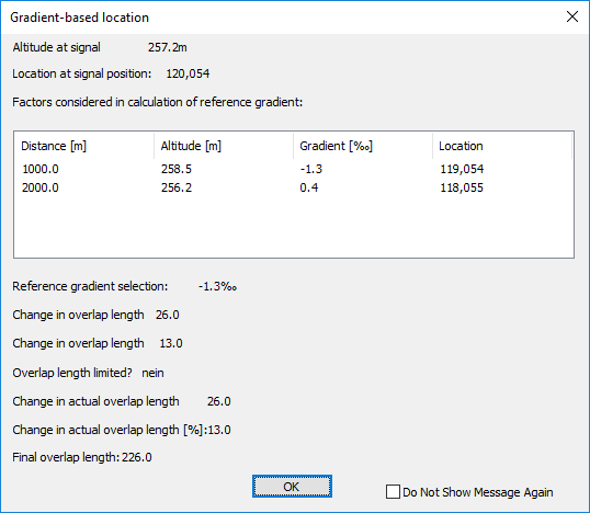
Illus.: Representation of the Calculation Results in the Dialog
7.'Move object along topology (Yes/No) <N>:' - If the object needs to be moved along the topology due to local conditions, the response should be 'Y', otherwise 'N' (default value 'N').
8.'Enter distance (positive value in working direction, negative value against working direction) <0.00>:' If the answer to point 4.7 is 'Y', the displacement needs to be entered here in meters.
oThe prompt 'Enter lateral distance in meters <3.85>:' requires the lateral distance of the signal from the center of the track. The default value is 3.85 meters.
5.By adjusting the allocated objects Signal frame, Signal aspect and the attributes, visible changes are displayed directly in the Preview (C). The button 'Zoom' (S) allows to view the signal in the drawing.
After the insertion in the section 'Signal' (A) the following attributes are decisive for further processing:
Nr. |
Attribute |
Impact |
1 |
Schirm: Signalsystem |
Determines the Signal System for which the signal has to be displayed. If no signal system has been selected, the signal system 'Ks' is assumed. |
2 |
Schirm: Art |
Depending on the selected type, the corresponding signal terms and signal type indicators are created automatically corresponding to the attribute 'Schirm: Signalsystem'. |
3 |
Schirm: Bedienart |
Definition of the Operating type and corresponding representation of the Main screen. |
4 |
Aktiv: Funktion |
Defines the function of the signal in the formation of track routes. |
Table: List of the key attributes to be documented which have an impact on further processing
6.With the Drop-down list 'View' (V) the visibility of the displayed attributes can be adjusted.
oWith the setting 'Reduced view' only a relevant part of the attributes of the signal is displayed.
oWith the setting 'Full view' all the attributes of the signal are displayed.
7.With the button 'Choose existing' (H) an existing signal can be selected in the drawing in order to display it for editing in the dialog.
oWhile editing the attributes, if necessary the F5 key should be pressed to actualize the mandatory fields after the respective entries.
8.The button 'Insert copy' (I) is used to insert a previously selected signal into the drawing as a new, identical signal. By activating the option 'Gradient-dependent positioning' (O) the insertion is performed with gradient-dependent positioning as described under point 4.
oAfter the insertion, the attributes of the new signal are displayed in the dialog.
oThe attributes should be adjusted accordingly.
9.To create a new signal at a mounting that remains in the drawing after deleting a signal, the button 'Create at signal mount' (J) is used to insert a new signal at the existing mounting. To do this, select the existing mounting in the drawing.
10.With the button 'New' (K) a new frame is created. The newly created frame is linked to the previously marked mounting using the attribute 'Signal mounting'.
11.With the button 'Delete' (L) selected frames are deleted.
12.The button 'New' (Q) is used to create a new Signal aspect for a previously selected frame.
13.With the button 'Delete' (R) one or more previously selected Signal aspects are deleted.
14.To create a new mounting on an existing mounting (e.g. mounting type 'Fundament' to mounting type 'Signalanordnung Mast'), select a mounting in the section 'Signal mounting' (B). Subsequently, a new mounting can be created with the button 'New' (D). The newly created mounting is linked to the previously marked mounting by the attribute 'Signal mounting'.
In order to interlink a individual frame of a signal with a standalone mounting, first select the appropriate frame in the section 'Frame' (N). Then use the button 'New' (D) to create a new mounting for the frame. If the frame was previously linked to another mounting, this link will be deleted. An application is e.g. a stand-alone subsidiary signal that belongs to a signal. At present, this construction is not visualized in the drawing, but the signal frame is still displayed at the mounting of the main screen.
15.To delete an existing Signal mounting, after marking one or more mountings in the section 'Signal mount' (B) the 'Delete' button (E) is used to delete the selected mountings.
ATTENTION: This functionality is only applicable for Signal mountings, where the value 'leer' is entered for the attribute 'Signal mounting'.
16.To assign the current signal to an existing mounting of another signal, first mark a mounting of the current signal in the section 'Signal mount' (B). Then the button 'Assign existing mount' (F) is used to select the signal in the drawing. Select the existing mounting of another signal in the drawing. The marked mounting is assigned to the mounting selected in the drawing.
This functionality is used to assign signals to an existing bracket. For a concrete description of how to create signals on brackets, see the page Example: Inserting at the Signal Brackets.
17.The button 'Delete' (U) is used to delete a Signal including the assigned Signal aspects, Signal frames and Signal mountings from the project.
18.Once the final positions of the entry signals are defined, if necessary the ranges of the Track Identifiers can be adapted subsequently, as described under PSO Area Object - Edit.