Example: Inserting a Shunting Signal at a Dwarf Mast

Contents
Process:
•Inserting a Shunting Signal using the example 60L105Y.
Requirements:
•see Signals - EPU
Description:
Using the example 60L105Y, the procedure for creating a shunting signal with a low mast (Dwarf Mast) is explained step by step.
After inserting the signal and editing the attributes in the dialog area 'Signal', the corresponding signal aspects of the screen and the signal type indicators are generated automatically. A separate signal frame is created for the designation plate. At the end, the signal mounting 'Fundament' is created for the signal.
It is described to which attributes have to be edited in order to ensure a correct view in the drawing and (at a later time) a complete export.
Procedure:
1.With the button 'New' (A) a new signal can be inserted, as described under Insertion of Signals. To edit this example, select the 'Leer' signal type.
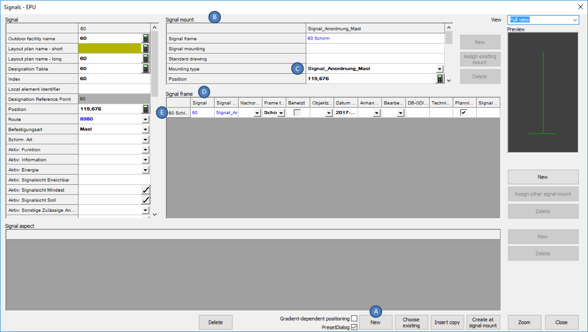
Illus.: Newly inserted Signal
oWhen inserting, select a point on the topological edge.
oThe Signal is generated with a Signal mount (B) ('Mounting type' (C) = 'Signalanordnung Mast') and an empty Signal frame (D) ('Frame type' (E) = 'Schirm').
2.For the Signal (F) the following attributes have to be edited:
Nr. |
Attribute |
Value |
1 |
Local element identifier |
105Y |
2 |
Befestigungsart |
Fundament |
3 |
Schirm: Bedienart |
Wb/zb |
4 |
Schirm: Art |
Sperrsignal |
5 |
Aktiv: Funktion |
Andere |
6 |
Aktiv: Information |
P-Hausen (Objekt Außenelementansteuerung) |
7 |
Aktiv: Energie |
P-Hausen (Objekt Außenelementansteuerung) |
8 |
Schirm: Dunkelschaltung |
nein (Strich) |
9 |
Schirm: Richtpunktentfernung |
200 |
10 |
Schirm: Signalsystem |
Ks |
11 |
Aktiv: Signalsicht Erreichbar |
200 |
12 |
Aktiv: Signalsicht Mindest |
120 |
13 |
Aktiv: Signalsicht Soll |
200 |
14 |
Schirm: Streuscheibe |
leer |
15 |
Schirm: Betriebsstellung |
leer |
Table: Attributes to be edited for the Signal
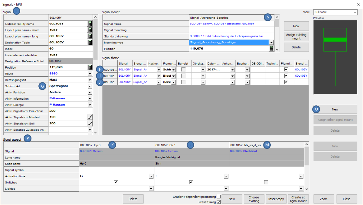
Illus.: Editing the Attributes for the Shunting Signal
oAfter changing the attribute 'Schirm: Art' (G), the corresponding signal aspect is automatically created.
▪The Signal aspect of the main screen ('Signal aspect ID' = 'Hp_0' (K) and 'Sh_1' (L)) are assigned to the Signal frame with the 'Frame type' = 'Schirm' (H).
▪For the signal type indicator ('Signal aspect ID' = 'Ms_ws_rt_ws' (M)) a separate signal frame with the 'Frame type' = 'Blechtafel' (I) is created.
3.For the automatically created Signal mounting (N) the following attributes should be edited:
Nr. |
Attribute |
Value |
1 |
Standard drawing |
S 8000.7.1, Bild= 8 (Objekt Regelzeichnung) |
2 |
Mounting type |
Signalanordnung Sonstige |
3 |
Obere Lichtpunkthöhe |
0.630 (Angabe in Metern, Dezimaltrenner ".") |
Table: Attributes to be edited for Signal Mounting
oFor the Dwarf Mast an 'Obere Lichtpunkthöhe' of below '2' needs to be entered. The corresponding foundation will be built later, see also Step 7.
For a high Shunting signal, a value greater than '2' needs to be entered for the 'Obere Lichtpunkthöhe'.
oThe Dwarf Mast can be created for panels, shunting signals and stand-alone auxiliary indicators.
4.To define the switch-ability of the signal aspects for the screen, after marking the signal frame 'Schirm' (H) for the assigned Signal aspect (K, L) in the area 'Signal aspect' (P) the following attributes have to be edited:
Nr. |
Signal aspect ID |
Lighted |
Switched |
Activation time |
Signal symbol |
1 |
Hp_0 |
leer |
ja |
G |
leer |
2 |
Sh_1 |
leer |
ja |
T |
leer |
Table: Creating Signal aspects for the Signal frame Screen
5.After marking the Signal frame 'Blechtafel' (I), the following attributes have to be edited for the assigned Signal aspect (M) in the area Signal aspect:
Nr. |
Signal aspect ID |
Lighted |
Switched |
Activation time |
Signal symbol |
1 |
Ms_ws_rt_ws |
leer |
leer |
leer |
leer |
Table: Attributes to be edited for the Signal frame Metal board (Signal type indicator)
6.To create a new signal frame for the Bezeichnungsschild (I), first mark the signal mounting with the 'Mounting type' = 'Signalanordnung Sonstige' (N). Then in the Signal frame area, use the 'New' (O) button to create a new signal frame. The following attribute needs to be edited:
Nr. |
Eigenschaft |
Wert |
1 |
Frame type |
Bezeichnungsschild |
Table: Attributes to be edited for the newly created Signal frame Designation plate
oFor the Designation plate, no signal aspects are created.
7.In order to lay the foundation, first mark the signal mounting with the 'Mounting type' = 'Signalanordnung Sonstige' (R). Then, use the button 'New' (T) to create a new signal mounting for the Fundament (S).
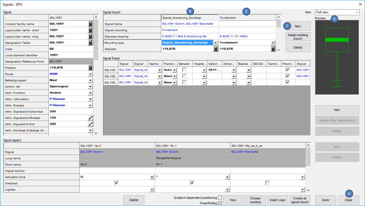
Illus.: Creating the Signal Mounting Foundation
For the Fundament (S) the following attributes have to be edited:
Nr. |
Attribute |
Value |
1 |
Mounting type |
Fundament |
2 |
Standard drawing |
S 8240.11.10, l= 600 (Objekt Regelzeichnung) |
3 |
Höhe Fundamentoberkante |
-0.100 |
Table: Attributes to be edited for the newly created Signal Mounting Foundation
oThe foundation is displayed in the Preview (V) only after the dialog is closed and reopened with the attributes of the Signal.
8.The button 'Close' (U) will close the dialog and displays the Signal in the drawing.
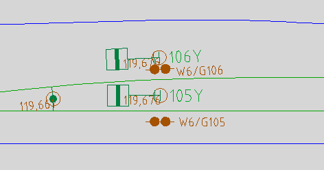
Illus.: Signal 60L105Y in the drawing