Insertion of Reference Points

Contents
Process:
•Insertion of Reference Points with the EPU-Object Inserter.
Requirements:
Description:
A Reference Point is represented in ProSig as a dot-like object located at the topological edge. The Reference Point is created, only when required.
In the PlanPro glossary, the object is formulated as follows:
Reference Point (Sonstiger_Punkt)
Reference point which is not defined by another point object.
The Object Reference Point (Sonstiger_Punkt) is created by the SCT planner, when there is no existing point object available to describe the reference point. In particular, the following are considered:
•Beginning of a Platform,
•Edge of a danger zone on the level crossing,
•End-of-train or -tip,
•Beginning of the area of a protection signal to be covered (e.g. movable bridge),
•Other Points (e.g. Merkpfahl, Laternenmast).
DB Rules and Regulations:
•End Overlap: Table of overlaps, column 2: 'Overlap to';
•Danger point: Danger point table, column 2: 'Danger point distance - reference danger point';
•Location of track clearance detection limit: dimension specification in the Signalling layout plan and Axle counter table, column 17: 'Reference point'.
Attribute Overlap pending authorization (ID_DWeg_Erlaubnisabhaengig)
Dependency of all overlaps - with this reference point as target - on the position of authorization of the block system at the end of which the linked block element is located.
The Overlap is only adjustable, if the authorization of the block element is directed towards the line.
DB Rules and Regulations: Block system table, column 11: 'Overlap pending authorization'
(Source: PlanPro Glossary)
Procedure:
1.Start EPU-Object Inserter and select the Object type 'Reference Point'.
Command Line: PRS_EPU_EINF
Ribbon: ProSig EPU -> Equipment SCT -> EPU-Object Inserter
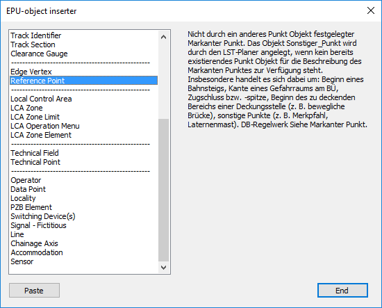
Illus.: Selection of the object type 'Reference Point' in the EPU-Object Inserter
2.The button 'Paste' inserts a new object 'Reference Point' into the drawing.
oDuring the insertion, select a point on the topological edge (PRS-TOPOLOGICAL EDGE layer).
oThe Reference point is a PSO-Point Object.
oAfter the creation, the reference point is displayed on the track set and stored on the layer PRS-REFERENCE POINT.
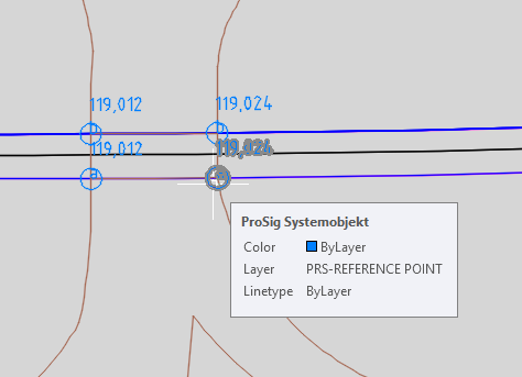
Illus.: Representation of a Reference Point in the Project Drawing
3.After the insertion, all relevant data should be specified using the function Edit Object(s).
Command Line: OE
Ribbon: ProSig EPU -> Tools -> Edit Object(s)
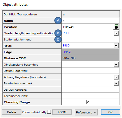
Illus.: Attributes of a Reference Point at a Danger zone border
oFor the Attribute 'Name' (A), the name of the reference point needs to be specified.
oFor the Attribute 'Overlap pending authorization' (B) a block element can be linked, if the reference point is the target of an overlap which depends on the authorization of the position of the block system.
oFor the Attribute 'Station platform end' (C) the corresponding object platform edge can be assigned, if the reference point marks the beginning of a platform edge.
4.The Reference point may be moved to its physical location laterally next to the topological edge, after the insertion over the grip on the main object.