Insertion of Sensors

Contents
Process:
•Insertion of Sensors with the EPU-Object Inserter.
Requirements:
Description:
In ProSig, a Sensor is represented as a dot-like object which is located at the topological edge. Depending on the type of sensor, the object is displayed in the project drawing.
Attention: Double sensors as part of an free detection system should be generated as Track Clearance with Axle Counter Sections, Step 5.
In the PlanPro glossary, the object is formulated as follows:
Sensor (Zugeinwirkung)
Technical system, capable of triggering a switching operation by the punctual control of a train.
With the Level crossing protection system, switch-on and switch-off points as well as contacts for efficiency circuit are designed in different ways depending on the type of manufacturer: The manufacturers Scheidt&Bachmann as well as PintschBamag use as train control vehicle sensors in the form of 8-shaped loops in the track. Switch-on points and contacts for efficiency circuit are usually formed from two loops, switch-off points from one loop. Only in exceptional cases the manufacturer PintschBamag will establish switch-on points with three loops. The manufacturer Siemens AG, on the other hand uses Axle counters comparable to so-called double sensors. For the model, regardless of the manufacturer-specific training, switch-on and switch-off points as well as contacts of the efficiency circuit are basically regarded as ONE train control.
DB Rules and Regulations:
•Type-specific Planning information and Technical messages;
•Planning Data:
oSignalling Layout Plan, Level Crossing-Layout plan,
oTrain detection plan.
(Source: PlanPro Glossary)
Procedure:
1.Start EPU-Object Inserter and Select the Object type 'Sensor'.
Command Line: PRS_EPU_EINF
Ribbon: ProSig EPU -> Equipment SCT -> EPU-Object Inserter
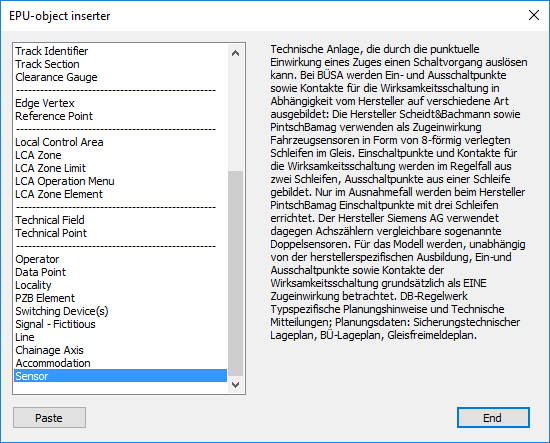
Illus.: Selection of the Object Type 'Sensor' in the EPU-Object Inserter
2.The button 'Paste' is used to create a new object 'Sensor' in the drawing.
oDuring the insertion a point on the topological edge (layer PRS-TOPOLOGICAL EDGE) needs to be selected. To insert a sensor or a loop in the quadrant, select the center between left and right to insert the object centrally on the topological edge as described under Dot-like PSO - Insertion at the Topological Edge.
oThe Sensor is a PSO-Point Object.
oAfter the creation, the sensor is displayed on the track set and stored on the layer PRS-SENSOR.
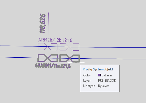
Illus.: Representation of Sensors as Double Loops in the Project Drawing
3.After the insertion, all relevant data have to be specified using the function Edit Object(s).
Command Line: OE
Ribbon: ProSig EPU -> Tools -> Edit Object(s)
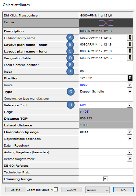
Illus.: Attributes of a Sensor of the Type 'Doppel-Schleife'
oFor the Attribute 'Local element identifier' (E) the name of the sensor can be specified optionally. Since the name of the sensor basically depends on the application, a manual override of this attribute is recommended in some cases. For this, the attributes 'Outdoor facility name' (A), Layout plan name - short (B), Layout plan name - long (C) and Designation Table (D) have to be adapted taking into account the Index (F), see also Editing And Displaying Complex Data - Object Identifier.
oFor the Attribute 'Type' (G), the type of sensor should be specified.
▪By selecting 'Isolierte Schiene (separat)', 'Isolierte Schiene (FMA genutzt)' and 'Sonstige' a circle is displayed as graphical representative.
▪For the selection 'Doppel-Schleife', 'Doppel-Sensor', 'Dreifach-Schleife', 'Einfach-Schleife' or 'Einfach-Sensor' the representation in the project drawing is according to the corresponding type.
▪For Doppel- or Dreifachschleifen, the other loops are located behind the first loop in the working direction, at the insertion point.
▪If the type 'Sonstige' is specified, a comment with corresponding explanations should be added.
oFor the Attribute 'Reference Point' (H) the corresponding object Signal, Switch Component or Derailer Component has to be assigned, when the sensor is inserted as train control at a prescribed distance from this object.