Creation of Gradient Data

Contents
Process:
•Create and Edit the Gradient Data in the ProSig Project.
Requirements:
Description:
Gradient change point and Ranges of gradient can be either imported from a Track Network Database (GND) or generated manually.
Gradient Change Point: Boundary points of Ranges of gradient, possess height and coordinate data (Layer PRS-GRADIENT CHANGE).
Ranges of Gradient: Areas limited by two gradient change points (Layer PRS-GRADIENT RANGE)
Supporting video sequence:
Neigungsbereich_erstellen.mp4 (Size: 3,3 MB)
Procedure:
1.Start the Ranges Editor.
Command Line: PRS_BAENDER
Ribbon: ProSig EPU -> Equipment ETCS -> Ranges Editor
2.Select the 'Gradient' tab.
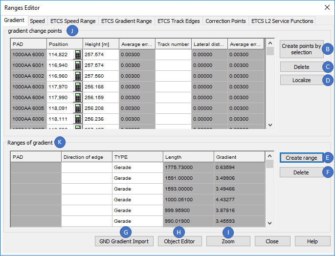
Illus.: Ranges Editor - Gradient Tab
Manual Creation of Gradient Change Points and Ranges of Gradient: continue with Step 3.
Automatic Creation of Gradient Change Points (Track Network Database exists): continue with Step 9.
3.The button 'Create points by selection' (B) is used to manually create gradient change points (Object type 'Gradient Change') in the drawing.
1.When inserting, select a point on the topological edge (Layer PRS-TOPOLOGICAL EDGE).
2.Any number of points can be selected.
3.Confirm the selection with the Enter key.
oAfter the insertion, the Gradient Change Points are displayed with their relevant attributes at the beginning of the List 'gradient change points' (J).
oThe Gradient change points are PSO which are stored as point objects on the layer PRS-GRADIENT CHANGE after creation.
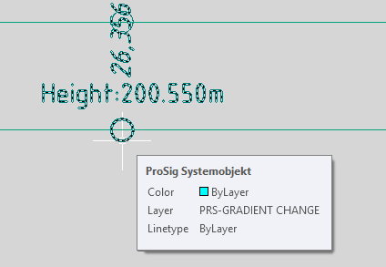
Illus.: Gradient Change Point in the Drawing
4.After the creation of the gradient change point, it is necessary to enter all relevant data using the object attributes.
Possibilities for the Input:
oDirect data input using the attributes in the List 'gradient change points' (J).
oMark an gradient change point in the List 'gradient change points' (J) and press the button 'Object editor' (H) (see also Step 13).
oAfter closing the Ranges Editor, the function Edit Object(s) is used to edit the object attributes on the gradient change point in the drawing.
Command Line: OE
Ribbon: ProSig EPU -> Tools -> Edit Object(s)
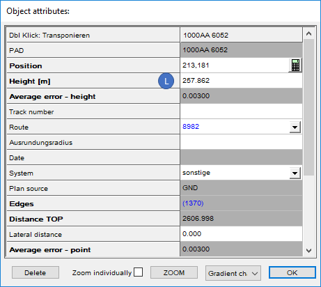
Illus.: Object Attributes of an Gradient Change Point
oFor the attribute 'Height [m]' (L) the height needs to be specified in meters.
5.With the button 'Localize' (D) you can assign gradient change points, if they are not automatically located during insertion, to their topological edge.
1.Select the button 'Localize' (D).
2.Select the gradient change point in the drawing to be located.
3.Select the topological edge at which the gradient change point should be located.
4.Repeat Steps 5.2 and 5.3 until all the gradient change points are located.
5.Exit the function with the Enter key.
6.For the manual creation of the Gradient range (Step 7), two Gradient change points are required. The Steps 3, 4 and if necessary 5 have to be executed again accordingly.
7.The button 'Create range' (E) is used to manually create an Gradient range in the drawing.
oTwo gradient change points have to be selected in the drawing, between which a connection exists on the topological edge. This connection is only allowed to run in one direction (i.e. without reversal).
oOnce the Gradient range is created, the attributes are displayed in the Ranges Editor dialog at the beginning of the List 'Ranges of gradient' (K).
oThe Gradient range is a PSO and when it is created, it is stored as a range object on the layer PRS-GRADIENT RANGE.
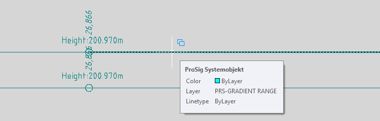
Illus.: Gradient Range in the Drawing
8.After the creation of the gradient range, all relevant data have to be entered using the object attributes.
Possibilities for the Input:
oDirect data input using the attributes in the List 'Ranges of gradient' (K).
oMark a gradient range in the List 'Ranges of gradient' (K) and press the button 'Object editor' (H) (see also Step 12).
oAfter closing the Ranges Editor, the function Edit Object(s) is used to edit the attributes of the gradient range in the drawing.
Command Line: OE
Ribbon: ProSig EPU -> Tools -> Edit Object(s)
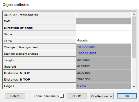
Illus.: Object Attributes of a Gradient Range
9.If the topology is created on the basis of a track layout imported from a Track network database, also the gradient data can be imported from the Track network database.
With the button 'GND Gradient Import' (G) the gradient data can be imported into the ProSig project after the track network database is specified.
oThe gradient change points are automatically generated and stored as dot-like PSO on the layer PRS-GRADIENT CHANGE.
oGenerally, the gradient change points are automatically located at the topological edge (layer PRS-TOPOLOGICAL EDGE). Points which are not located automatically can be located later with the button 'Localize' (D) (see also Step 5). To check the location, continue with Step 10.
10.The Location Report is used to check the location of gradient change points.
Command Line: VERORTE_REPORT
Ribbon: ProSig EPU -> Tools -> Services -> Location Report
oGradient change points that are not located usually do not lie exactly on the topology. They are located by moving them vertically onto the topology.
oThe gradient ranges in the area of a non-located gradient change point must be visually checked. Where the topology (layer PRS-TOPOLOGICAL EDGE) is not covered by gradient ranges (PRS-GRADIENT RANGE), the incorrect ranges have to be deleted and replaced by the correct ones.
11.With the button 'Delete' (C) the marked gradient change point can be deleted. If the gradient change point is assigned to a gradient range, it also be deleted.
oMark an object in the list 'gradient change points' (J).
oSelect the button 'Delete' (C).
oMarked gradient change point is removed from the list (J) and deleted from the drawing. The associated gradient range is then removed from the list (K) and deleted from the drawing.
12.With the button 'Delete' (F) the marked gradient range can be deleted.
oMark an object in the list 'Ranges of gradient' (K).
oSelect the button 'Delete' (F).
oMarked gradient range is removed from the list 'Ranges of Gradient' (K) and deleted from the drawing.
13.With the button 'Object Editor' (H) the attributes of marked objects can be displayed and edited.
oMark an object in the list 'gradient change points' (J) or 'Ranges of gradient' (K).
oSelect the button 'Object Editor' (H).
oAttributes of the selected object are displayed for editing.
14.With the button 'Zoom' (I) the marked object in the drawing can be marked and zoomed.
oMark an object in the List 'gradient change points' (J) or 'Ranges of gradient' (K).
oSelect the button 'Zoom' (I).
oThe selected object is marked and zoomed in the drawing.