Track Paths

Contents
Process:
•Planning of track paths
•Defining attributes for track paths
Requirements:
see Track Paths, Overlaps, Track Routes and Flank Protection
Description:
In ProSig, a track path is a PSO Area Object, where the start and destination of the track path are always at a signal or operating point (virtual signal as destination; e.g. end of station).
In the PlanPro glossary, the object is formulated as follows:
Track Path (Fstr_Fahrweg)
Unbranched section on the track network that serves as the basis for the part of a track route being traveled on or the overlap of a track route.
The start is always at a signal, the destination is
•at a signal for the part that is being traveled on,
•at an overlap (or distance to danger point) in a position markers.
For main and shunt routes with the same track path, the same instance of the track path can be used; for exceptions see track route dependency.
Note for modeling an overlap, if the position markers is a switch toe: If an overlap switch toe approaches and the switch toe is the end of the overlap, then
•the area object track path ends at the end of the edge before the switch toe,
•the position markers is the point object switch component, which refers to the following edges.
Thus the end of the area object and the position markers lie on different edges (each with a distance of 0 to the node), yet geographically they describe the same point.
DB Rules and Regulations: In today's planning work, there is only an implicit way to find the path through the specification
•for the part of the start, destination and decision points in the shunting route table,
•for the overlap and distance to danger point of start and destination and all switches in the table of overlaps and danger point table respectively.
(Source: PlanPro Glossary)
Supporting video sequence:
Erstellung_Fahrwege.mp4 (Size: 8,0 MB)
Procedure:
1.To Create a track path, select the sub-tab 'Create' on the main tab 'Track Paths'.
To Edit the attributes of an existing track path, continue with Step 8.
Command Line: PRS_FAHRSTRASSE
Ribbon: ProSig EPU -> Equipment SCT -> Track routes
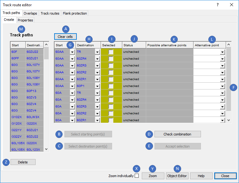
Illus.: Track paths to be created with unchecked status
oIf track paths already exist in the planning project, they are displayed in the list of 'Track paths' (M). If no track paths have been created yet, the list (M) will be empty.
oTo display the attributes, after selecting an object in the list (M) with the button 'Object Editor' (N) continue with Step 6.
oAfter selecting objects in the list (M), they can be selected and zoomed using the button 'Zoom' (Y) in the drawing. The zoom can be set individually or together, depending on the setting of the check box 'Zoom individually' (X).
oAfter selecting track paths in the list (M), they can be deleted with the button 'Delete' (Z).
2.The Button 'Select starting point(s)' (B) is used to select a start signal.
oIf several track paths have to be created at the same time, several objects can also be selected.
oWhen selecting for the track path start, irrelevant objects are filtered out. In particular, ensure that the attributes 'Schirm: Art' and 'Aktiv: Funktion' of the start signal are assigned accordingly.
oWhen the dialog is reopened, the selected starting points are displayed in the list of possible Start-/ Destination combination (F) under the attribute 'Start' (G).
oIf linked objects are marked in the list (F) (columns 'Start', 'Destination'), the attributes of these objects can be displayed by clicking the button 'Object Editor' (N).
oIf linked objects are selected in the list (F) (columns 'Start', 'Destination'), the objects in the drawing can be selected and zoomed with the button 'Zoom' (Y). The zoom can be set individually or together, depending on the setting of the check box 'Zoom individually' (X).
3.The Button 'Select destination point(s)' (C) is used to select a destination signal or a fictitious signal (operating point).
oIf several track paths have to be created at the same time, several destinations can also be selected.
oWhen selecting a track path destination, irrelevant objects are filtered out. In particular, ensure that the attributes 'Schirm: Art' and 'Aktiv: Funktion' of the destination signal are assigned accordingly.
oWhen the dialog is reopened, the selected destinations are displayed in the list of possible Start-/ Destination combination (F) under the attribute 'Destination' (H).
oThe Attribute 'Status' (J) of the possible Start-/ Destination combination is still 'unchecked'.
4.With the button 'Check combination' (D) the possible Start- / Destination Combination in List (F) are checked.
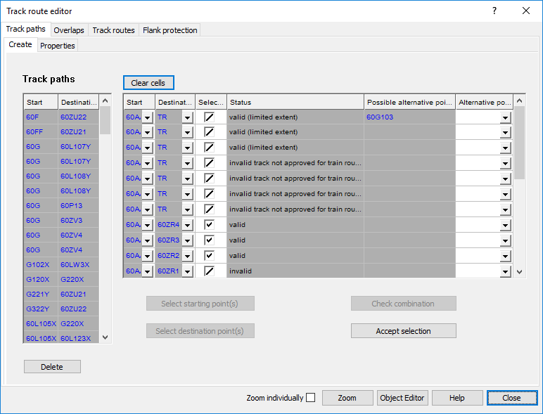
Illus.: Track paths to be created, checked
oThe Attribute 'Status' (J) changes from 'unchecked' to one of the following statuses:
Status |
Significance |
|---|---|
valid |
valid track path |
valid (limited extent) |
track path between start- and destination point is found, validity to be checked by user |
invalid |
invalid track path |
invalid track not approved for train routes |
track paths leads over a track that is not permitted for freight trains, passenger trains or suburban trains (depending on the setting of the associated options for the underlying object 'Track Identifier', see Specifying the Track Identifiers within Train Stations) |
invalid deviating directions |
start signal and destination signal of the track paths are signaling opposite directions |
present |
track path already exists in the project |
Table: List of statuses and their significance in the validation of Track paths
oValid track paths are automatically selected (I). Existing, limitedly valid or invalid track paths are automatically deselected.
oRestricted valid track paths that should be included in the project, have to be selected separately.
oTrack paths that are valid but should not be included in the project, have to be deselected.
oPossible deviation points through a switch or a track section are listed in the attribute 'Possible alternative points' (K).
oThe applicable deviation point can be selected from the drop-down 'Alternative point' (L).
5.With the button 'Accept Selection' (E), the selected routes are created. The track paths are displayed with the attributes 'Start' (G) and 'Destination' (H) in the list of Track paths (M).
oIn the case of a track route with a dependent key release instrument and a shunt route (without Ssp) with the same start and destination, the track path should be defined twice. This procedure is currently not supported.
oThe track path is a PSO and is stored as an area object on the Layer PRS-TRACK PATH once it is created.
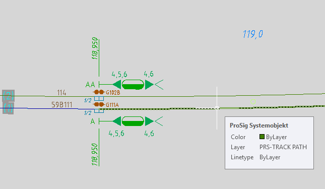
Illus.: Created Track path in the drawing
6.After marking a track path in the list (M), the attributes of the track path can be displayed by clicking the button 'Object Editor' (N). If several track paths are selected in the list (M), the attributes of all selected objects are displayed simultaneously.
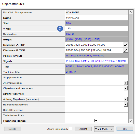
Illus.: Attributes of a Track Path
oThe objects lying on the track path are stored in the corresponding attributes.
oFor the attribute 'V max' (O), enter the speed which would have been driven on main routes with this part without restriction by Zs3.
7.Use the button 'Clear cells' (A) to clear the list (F) before re-creating Start- / Destination combinations. (requirement for Step 1.)
8.To define the assignments for Stop prevention, the Clearance - explicit and the Dependent key release instrument of an existing track path, select the sub-tab 'Properties' on the main tab 'Track paths'.
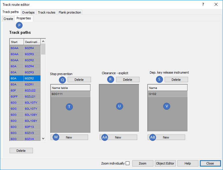
Illus.: Tab 'Properties' for the marked Track path A.ZR2
9.In the list 'Track paths' (P), select the track path for which the attributes should be defined.
10.With the button 'New' (W), it is possible to assign a track clearance section in the drawing to the marked track path for Stop prevention.
oOne or more Track clearance sections can be selected in the drawing. The selection is confirmed with the Enter key or by clicking in the drawing.
oAfter confirming the selection, the name of the track clearance section is displayed in the list (T).
oThis attribute corresponds to column 6 of the rail line string table.
11.After marking the track clearance section in the list (T), the links as a Stop prevention to a track path can be removed with the button 'Delete' (Q). The corresponding objects 'Track Clearance Section' will then remain in the drawing.
12.With the button 'New' (AA), it is possible to assign a track clearance section in the drawing to the track path for the Clearance - explicit.
oOne or more Track clearance sections can be selected in the drawing. The selection is confirmed with the Enter key or by clicking in the drawing.
oAfter confirming the selection, the name of the track clearance section is displayed in the list (U).
13.After marking the track clearance section in the list (U), the links for Clearance - explicit to a track path can be removed with the button 'Delete' (R). The corresponding objects 'Track Clearance Section' will then remain in the drawing.
14.With the button 'New' (AB), it is possible to assign a dependent key release instrument to the marked track path in the drawing.
oOne or more Key release instruments can be selected in the drawing. The selection is confirmed with the Enter key or by clicking in the drawing.
oAfter confirming the selection, the name of the key release instrument is displayed in the list (V).
oThis attribute corresponds to column 5 of the rail line string table.
15.After marking key release instruments in the list (V), the links as Dependent key release instrument to a track path can be removed with the button 'Delete' (S). The corresponding objects 'Key Release Instrument' will then remain in the drawing.