Planning Track Paths, Overlaps, Track Routes and Flank Protection

Contents
Process:
•Planning of Track paths, Overlaps, Track routes and Flank protection.
Requirements:
Description:
The Track route editor serves to facilitate the planning of track routes and supports the following functional sections:
•Defining the appropriate Track Routes
•Setting up the Flank Protection
For each section, the following tabs are available, which are explained below.
Procedure:
1.The Planning of Track paths, Overlaps, Track routes and Flank protection is supported by the function 'Track Routes'.
Command Line: PRS_FAHRSTRASSE
Ribbon: ProSig EPU -> Equipment SCT -> Track Routes
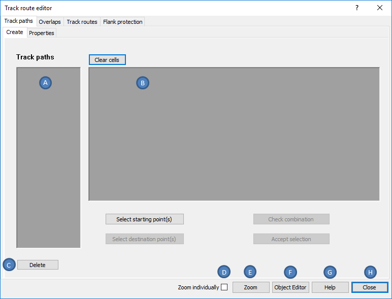
Illus.: Track route editor Dialog
All Registers (tabs) in the dialog follow the same layout. The General functionalities are explained below:
oRight-click with the mouse in a value field or on a row/column header of a list (A, B) to open a Context Menu.
oIn all lists, a multiple selection of objects is possible (exception: register 'Flank Protection - Create', list 'Request objects'):
▪by selecting with the mouse and simultaneously pressing the Control key or
▪by selecting with the arrow keys and simultaneously pressing the Shift key.
oThe button 'Delete' (C) deletes selected objects in the list (A).
oIf the check box 'Zoom individually' (D) is not checked, the button 'Zoom' (E) simultaneously zooms all selected objects from the previously used list and highlights them in color. By pressing the Enter key or clicking in the drawing, the dialog opens again.
oIf the check box 'Zoom individually' (D) is checked, the button 'Zoom' (E) zooms in on all selected objects from the previously used list and highlights them in color. By pressing the enter key or clicking in the drawing, the next object to be zoomed is displayed. If all objects are displayed, the dialog is opened again by pressing the Enter key or clicking in the drawing.
oThe button 'Object Editor' (F) displays the object attributes of the selected objects and that can be edited. Only the object attributes of an object type are displayed in the 'Object Attributes' dialog. If objects of different object types are selected, the object type can be changed using the selection list at the bottom of the dialog. The view is then updated accordingly.
oThe button 'Help' (G) opens the ProSig help which describes about the current register.
oThe button 'Close' (H) closes the dialog. Any changes to the objects are directly applied.