Flank Protection

Contents
Process:
•Planning of Flank Protection
•Processing of Dual-protection Switch
•Creation of Safety zones
Requirements:
see Track Paths, Overlaps, Track Routes and Flank Protection
Description:
The Flank protection object is a logical object represented in the table of flank protection. The Flank protection can be generated either for the track routes and their switches or only for the switches.
In the PlanPro glossary, the object is formulated as follows:
Flank Protection (Fla_Schutz)
Representation of the technical measures to ensure flank protection.
All measures taken to prevent rolling stock from entering an area that needs to be secured via track paths (Track route or Local control area).
There are basically three types of Flank protection:
•Directly: The Flank protection is provided by an adjacent element (direct acting: Switch, Derailer / indirect acting: Stop indicating signal / SPAD (Signal passed at danger)). (flank protection provided by points, derailers and signals)
•Waiver: The Flank protection is provided by operational measures; technically, this is not required. (flank protection provided by operative exclusions (non-technical))
•Transfer: The Flank protection is passed on to a flank protection call transfer point, which in turn ensures that the flank protection is provided. (flank protection provided by points, derailers and signals)
DB Rules and Regulations:
•819.0505
(Source: PlanPro Glossary)
Procedure:
1.To Create Flank protection, select the sub-tab 'Create' on the main tab 'Flank protection'.
To Display and edit dual-protection cases continue with Step 15.
To Create monitored Safety zones for the flank protection, continue with Step 18.
Command Line: PRS_FAHRSTRASSE
Ribbon: ProSig EPU -> Equipment SCT-> Track Routes
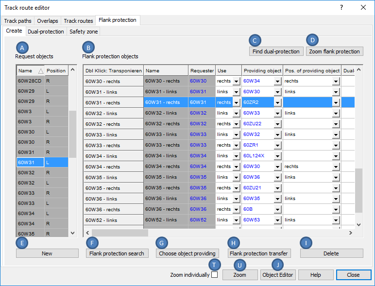
Illus.: Requesting objects and associated flank protection objects
2.In the list 'Request objects' (A), select the switch in the corresponding position for which flank protection should be requested.
3.The Button 'New' (E) creates a new flank protection object for the selected requesting object. The flank protection search is performed automatically and the determined values are entered in the list 'Flank protection objects' (B) in the object attributes of the flank protection object.
4.With the button 'Flank protection search' (F), the automatic flank protection search can be executed again once changes have been made to the object data.
5.With the button 'Choose object providing' (G) it is possible to change the entry in the list 'Flank protection objects' (B), column 'Providing object' by selecting the object in the drawing.
oSelect an object Switch element (Switch, Single slip, Double slip, Derailer) or Signal that offers flank protection.
6.With the button 'Flank protection transfer' (H), it is possible to change the entries in the list 'Flank protection objects' (B), Columns 'Providing object transfer L' and 'Providing object transfer R' by selecting the object in the drawing.
oSelect an object Switch element (Switch, Single slip, Double slip, Derailer) that provides flank protection.
7.Repeat the Steps 2 to 4 (and possibly 5 and 6) for all switches in the list (A).
8.With the button 'Delete' (I), the selected Flank protection object can be deleted from the list (B).
9.With the button 'Find dual-protection' (C), a check mark is automatically set in the column 'Dual-protection' if an flank protection object has dual protection. The dual protection cases can be handled subsequently via the sub-tab 'Dual-protection', see Step 15.
10.With the button 'Object Editor' (J), the object attributes for a flank protection object which has been previously marked in the list 'Flank protection objects' (B) (marking of the entire line) are displayed. If several flank protection objects are selected in the list (B), the object attributes of all selected objects are displayed simultaneously.
 |
 |
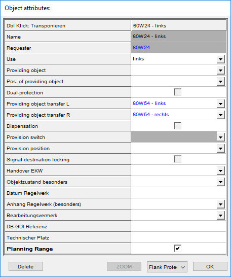
Illus.: Attributes of a Flank protection objects with Flank protection transfer |
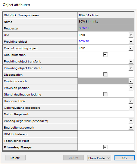
Illus.: Attributes of a Flank protection objects with Dual-protection |
11.If linked objects are marked individually in the list 'Flank protection objects' (B) (Columns 'Requester', 'Providing object', 'Providing object transfer L', 'Providing object transfer R', 'Provision switch', 'Handover EKW'), by clicking the button 'Object Editor' (J) the object attributes of these objects can be displayed.
12.With the button 'Zoom flank protection' (D), the requesting and bidding objects of previously marked flank protection objects in the list 'Flank protection objects' (B) are simultaneously zoomed and colored. By pressing the Enter key or by clicking on the drawing, the next flank protection object to be zoomed is displayed. Once all flank protection objects are displayed, pressing the Enter key again or by clicking in the drawing opens the dialog again.
13.After selecting the flank protection objects in the list 'Flank protection objects' (B), it is possible to select and zoom these objects via the button 'Zoom' (U) in the drawing. The zoom takes place for all linked objects (Columns 'Requester', 'Providing object', 'Providing object transfer L', 'Providing object transfer R', 'Provision switch', 'Handover EKW') individually or together, depending on the setting of the check box 'Zoom individually' (T).
14.If linked objects are marked individually in the list 'Flank protection objects' (B) (Columns 'Requester', 'Providing object', 'Providing object transfer L', 'Providing object transfer R', 'Provision switch', 'Handover EKW'), with the button 'Zoom' (U) the objects in the drawing can be marked and zoomed. The zoom takes place individually or together, depending on the setting of the check box 'Zoom individually' (T).
15.To Display and edit dual-protection cases, select the sub-tab 'Dual-protection' on the main tab 'Flank protection'. The description of the behavior of the dual-protection switches is available here, when both positions (left and right) of a switch flank protection are requested simultaneously.
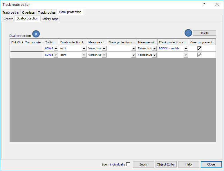
Illus.: Display of the existing Dual-protection Switches in the Project
oIn the list 'Dual-protection' (K), all objects are displayed for which the attribute 'Dual-protection' is checked in the List 'Flank protection objects' (B) on the main tab 'Flank protection', sub tab 'Create'.
16.In the list 'Dual-protection' (K), the object attributes can be edited according to the entries in the dual-protection table.
17.With the button 'Delete' (L), the marked objects in the list 'Dual-protection' (K) are deleted.
18.To Create monitored Safety zones for the flank protection, select the sub-tab 'Safety zone' on the main tab 'Flank protection'.
The Flank protection section is the section of track between the route-related interlocking element seeking flank protection and that which provides the flank protection.
| If flank protection is provided, then the flank protection area is generally maintained free. |
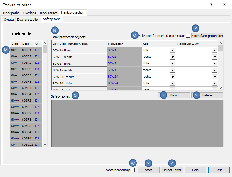
Illus.: Representation of Flank protection objects with their associated Safety zones
oThe list 'Track routes' (M) displays all existing track routes in the project.
oIn the list 'Flank protection objects' (N), all flank protection objects existing in the project are displayed with their respective attributes, when the check mark is not set for 'Selection for marked track route' (O).
oIn the list 'Flank protection objects' (N), for a track route marked in the list (M), all existing flank protection objects with their attributes are displayed, when the check mark is set for 'Selection for marked track route' (O).
19.To zoom flank protection objects that have been previously marked in the list 'Track routes' (N) with the button 'Zoom flank protection' (P) see also Step 12.
20.In the list 'Flank protection objects' (N), a Flank protection object is selected for which a safety zone will be created.
21.With the button 'New' (R) one or more track clearance sections (Layer PRS-TRACK CLEARANCE SECTION) can be selected in the drawing which represent the safety zone for a marked Flank protection object.
22.The list 'Safety zones' (Q) displays the assigned Safety zones with their attributes.
23.With the button 'Delete' (S), the safety zones marked in the list (Q) can be deleted.