Defining the Limits of a Local Control Area Zone

Contents
Process:
•Defining the Limits of a LCA Zone
Requirements:
•Creation of Local Control Area Zones
Description:
The Limit of a Local control area zone (LCA Zone Limit) is a dot-like object located at the topological edge.
In the PlanPro glossary, the object is formulated as follows:
LCA Zone Limit (NB_Zone_Grenze)
Limit of the LCA Zone opposite to the adjacent area of the Zone.
The LCA Zone is delimited by means of (technical) flank protection against the adjacent area (CBI or another zone).
Border elements form signals, switches or derailers which are closed in the respective flank protection position. For the local control area adjacent to the LCA zone, the TM 2010-388 I.NVT 3 'Planning rules for operating areas - Interfaces for interlocking areas' should be observed.
DB Rules and Regulations:
•TM 2010-388 I.NVT 3
The specification of border element outside the LCA Zone can be found in the Non-remote operations table, column 7.
(Source: PlanPro Glossary)
Procedure:
1.Start the function EPU-Object Inserter and select the Object type 'LCA Zone Limit'.
Command Line: PRS_EPU_EINF
Ribbon: ProSig EPU -> Equipment SCT -> EPU-Object Inserter
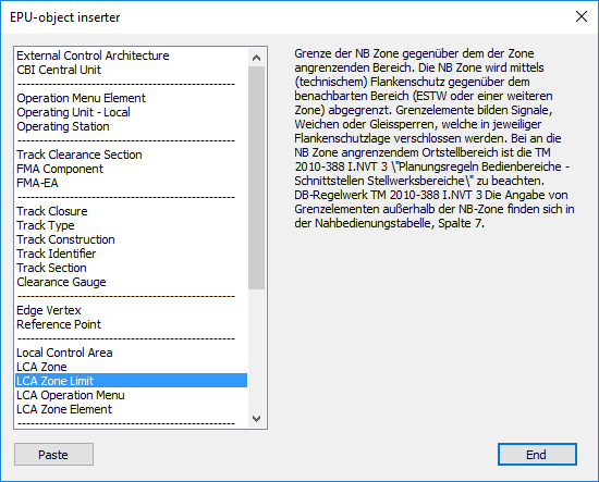
Illus.: Selection of the Object type LCA Zone Limit in the EPU-Object Inserter
2.With the button 'Paste' a new object 'LCA Zone Limit' can be inserted into the drawing.
oWhen inserting, select a point on the topological edge (layer PRS-TOPOLOGICAL EDGE). Select the point which is identical to the location point of the corresponding border element (Signal, Switch or Derailer).
oThe Object LCA Zone Limit is a PSO and is stored on the Layer PRS-LCA ZONE LIMIT.
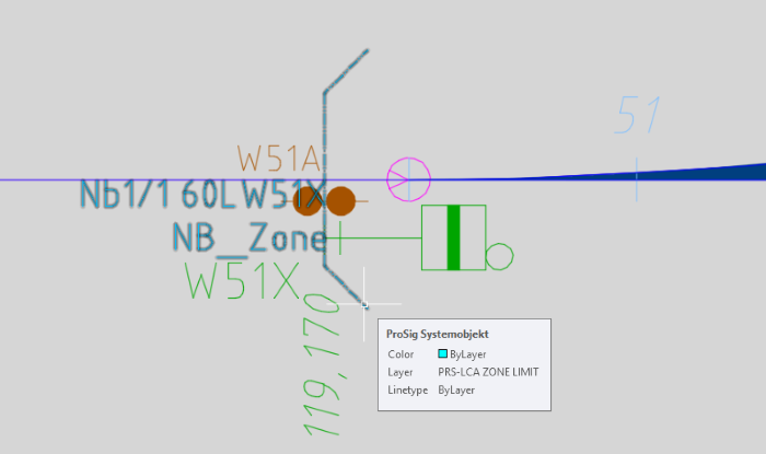
Illus.: Representation of a LCA Zone Limit in the drawing
3.After the insertion, all relevant data can be specified using the function Edit Object(s).
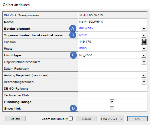
Illus.: Object Attributes of a LCA Zone Limit
oThe Attribute 'Border element' (A) is used to specify the object that represents the border of the LCA zone. When selecting a Switch or Derailer, it is important to select the appropriate Switch component. For assigning objects using the attributes, see also Editing And Displaying Complex Data - Assigning Objects.
oFor the Attribute 'Superordinated local control zone' (B), select the LCA Zone for which the limit is set.
oIn the Attribute 'Limit type' (C) the type of the adjacent area of the LCA Zone should be selected. Depending on the type of adjacent area set, the (technical) flank protection should be planned accordingly.
oBy selecting the attribute 'Show link' (D) the linking of the LCA Zone with the corresponding Local control area can be displayed.