Generate Topology

Contents
Prozess:
•Generieren der Gleistopologie
•Prüfen der Topologie und ggf. Korrektur
Voraussetzung:
•Importieren der Gleislage aus GND bei einer Neuplanung auf Basis einer GND-Datei im *.mdb-Format
oder
•Importieren der Gleislage aus einer ASCI-Bahn-Datei bei einer Neuplanung auf Basis einer Trassierungsdatei im *.aba-Format
oder
•Importieren der Gleislage aus einer *.tra-Datei bei der Neuplanung auf Basis einer Trassierungsdatei im *.tra-Format
oder
•Extrahieren der Gleislage bei der Migration eines Projekts aus der Version 6
Beschreibung:
Wenn sichergestellt ist, dass alle Gleislageelemente (Linien, Bögen und Polylinien) eindeutig miteinander verknüpft sind, kann die Topologie der Gleislage im Sicherungstechnischen Lageplan erstellt werden.
Beim Generieren der Topologie werden die vorhandenen Linien, Bögen und Polylinien der Gleislage gelöscht und in GEO Kanten mit den zugehörigen GEO Knoten und GEO Punkten umgewandelt. Neue topologische Kanten und Knoten werden erzeugt. Die topologischen Knoten erhalten hierbei Markierungen je nach Knotentyp und sind anschließend zu prüfen.
Falls Korrekturen aufgrund von Lücken, überlappenden oder doppelten Elementen erforderlich sind, können diese an den GEO Kanten vorgenommen werden, siehe hierzu auch Aktualisieren der Topologie.
Unterstützende Filmsequenz:
Generieren_der_Topologie.mp4 (Größe 1,8 MB)
Vorgehensweise:
1.Die Funktion 'Topologie generieren' starten.
Befehlszeile: TOPO_GEN
Multifunktionsleiste: ProSig EPU -> Gleislage/Topologie -> Topologie generieren
oNach Aufruf der Funktion erfolgt die Abfrage 'Objekte manuell auswählen (Nein wählt alle Objekte) (Ja/Nein) <N> :'
▪Soll nur ein Teil der Gleislage eingelesen werden, ist hier mit 'Ja' zu bestätigen. Anschließend kann eine Auswahl der Gleislageelemente vorgenommen werden.
▪Wird die Abfrage mit 'Nein' bestätigt, werden alle vorhandenen Gleislageelemente in das Projekt eingelesen. Diese Option ist beim erstmaligen Erzeugen der Topologie auszuwählen.
oDie zuvor vorhandenen Linien, Bögen und Polylinien werden gelöscht und wie im nächsten Schritt beschrieben in GEO Kanten mit zugehörigen GEO Knoten und Punkten umgewandelt. Die Topologie wird auf Basis der Geoinformationen generiert.
2.Nach dem Erzeugen der Topologie werden die GEO Kanten auf dem Layer PRS-GEO KANTE abgelegt. Die topologischen Kanten und Knoten werden auf den jeweiligen Layern PRS-TOPOLOGISCHE KANTE und PRS-TOPOLOGISCHER KNOTEN abgelegt.
oDie Eigenschaft 'Knotentyp' der topologischen Knoten wird automatisch ermittelt. Topologische Knoten werden automatisch mit Symbolen versehen entsprechend des ermittelten Knotentyps.
oFür die Knotentypen werden die separaten Layer PRS-TOPOLOGISCHER KNOTEN-KNOTENTYP-BETRACHTUNGSENDE und PRS-TOPOLOGISCHER KNOTEN-KNOTENTYP-WEICHE erzeugt. Für die spätere Planung können diese Layer separat ausgeschaltet werden.
oDie Darstellung des Knotentyps ist nur symbolisch und entspricht z. B. beim Knotentyp 'Weiche' nicht immer der Weichenrichtung.
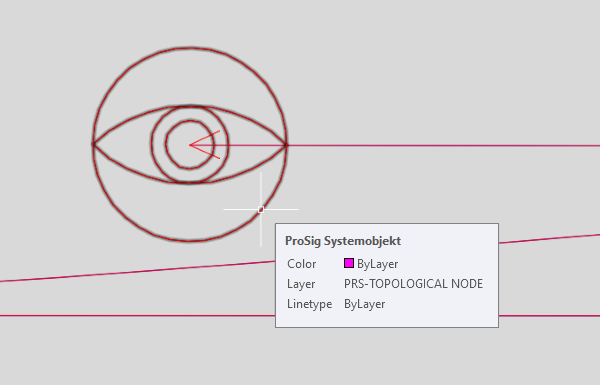
Bild: Darstellung eines topologischen Knotens vom Typ 'Betrachtungsende'
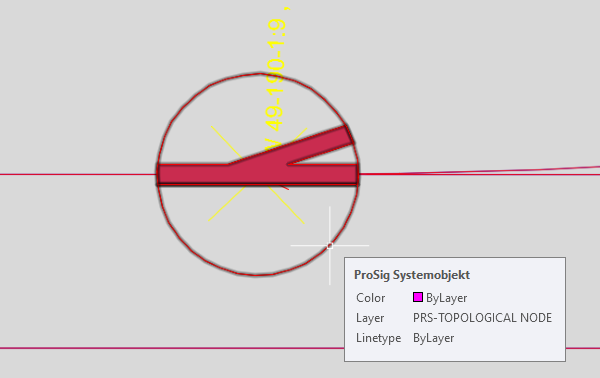
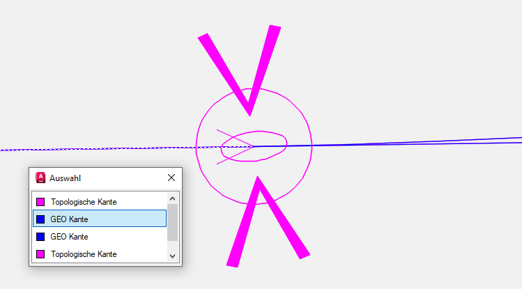
Bild: Darstellung eines topologischen Knotens vom Typ 'Weiche' für eine Weiche
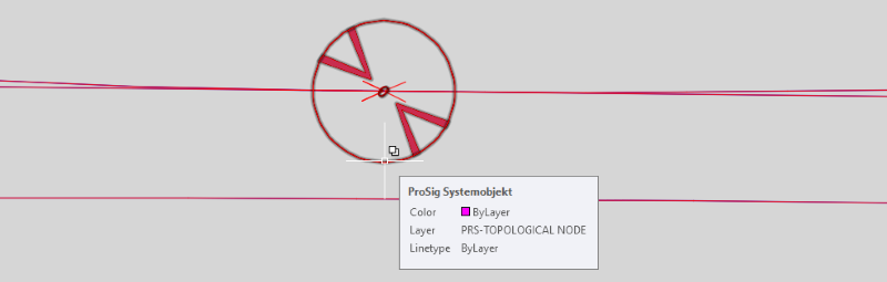
Bild: Darstellung topologischer Knoten vom Typ 'Weiche' für zwei Weichen (Weichenspitze an Weichenspitze)
3.Anschließend ist die Topologie zu prüfen. Dazu kann die Funktion Topologie prüfen verwendet werden. Topologische Knoten werden hierbei nacheinander gezoomt und die der Topologie zugrunde liegenden GEO Kanten können ggf. im Nachgang bearbeitet werden.
Befehlszeile: TOPO_CHECK
Multifunktionsleiste: ProSig EPU -> Gleislage/Topologie -> Topologie prüfen
oSind alle dargestellten Knotentypen wie erwartet, kann mit dem nächsten Schritt im Planungsprozess fortgefahren werden.
oSind einige der dargestellten Knotentypen nicht wie erwartet, weiter bei Schritt 4.
4.Sind beim Prüfen der Topologie Stellen aufgefallen, bei denen der Knotentyp nicht der erwarteten Darstellung entspricht, sind diese Stellen wie nachfolgend beschrieben zu behandeln.
Im Folgenden werden mögliche Fälle für eine zu korrigierende Gleislage erläutert. Vor der Korrektur der Gleislage ist zusätzlich zu den auf der Seite ProSig Planungssystem genannten Systemvariablen die wechselnde Auswahl (AutoCAD-Systemvariable SELECTIONCYCLING = 2) zu aktivieren:
oFall 1: Lücke in der Gleislage:
Bei der Bearbeitung der topologischen Knoten ist zu beachten, dass Symbole für Betrachtungsenden nur an echten Betrachtungsenden oder Gleisenden vorhanden sein dürfen. Es ist zu prüfen, ob ggf. eine Lücke in der Gleislage vorliegt.
1.Die entsprechenden GEO Kanten in Linien, Bögen oder Polylinien umwandeln wie unter Manuelles Bearbeiten von GEO Kanten, Schritt 1 und 2 beschrieben.
2.Die Lücke in der Gleislage durch Ziehen der Griffe der Gleislageelemente korrigieren.
 |
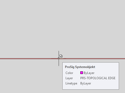 |
Bild: Gleislage mit Lücke vor der Korrektur |
Bild: Darstellung der Topologie nach der Aktualisierung in Schritt 5 |
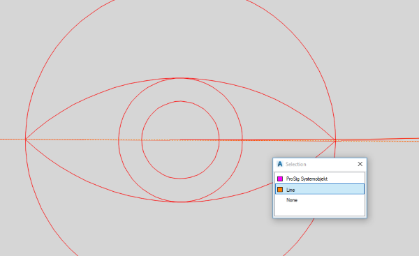
oFall 2: Nicht gebrochenes Gleiselement am Weichenabzweig:
Wird ein Knoten vom Typ 'Betrachtungsende' an einem Weichenabzweig dargestellt, treffen hier möglicherweise nicht drei Kanten aufeinander. Es ist zu prüfen ob das durchgehende Gleiselement ggf. an der entsprechenden Stelle zu brechen ist.
1.Die entsprechende GEO Kante, an der das durchgehende Gleis aufgebrochen werden soll, in Linie, Bogen oder Polylinie umwandeln wie unter Manuelles Bearbeiten von GEO Kanten, Schritt 1 und 2 beschrieben.
2.Das Gleislageelement aufbrechen am gewünschten Punkt, z. B. mit der AutoCAD Funktion 'An Punkt brechen' (ANPUNKTBRECH).
3.Prüfen, dass am gewünschten Weichenknoten die Gleislageelemente exakt aufeinander treffen. Dieses kann durch Ziehen der Griffe der Gleislageelemente korrigiert werden.
 |
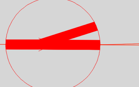 |
Bild: Gleislage mit nicht gebrochenem Gleiselement am Weichenabzweig vor der Korrektur |
Bild: Darstellung der Topologie nach der Aktualisierung in Schritt 5 |
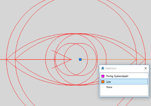
oFall 3: Doppeltes Gleiselement am Weichenanfang:
Werden Knoten vom Typ 'Weiche' am Weichenanfang dargestellt wie im Fall Weichenspitze an Weichenspitze, ist möglicherweise eine doppelte GEO Kante am Weichenanfang vorhanden.
Es ist zu prüfen welche der GEO Kanten am Weichenanfang entfernt werden kann. Die GEO Kante kann nach dem Markieren in der Zeichnung gelöscht werden.
 |
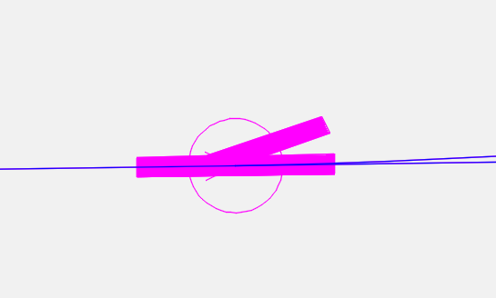 |
Bild: Gleislage mit einer doppelten GEO Kante am Weichenanfang |
Bild: Darstellung der Topologie nach der Aktualisierung in Schritt 5 |
5.Nach Korrektur der Gleislage ist die Topologie erneut zu erstellen, siehe hierzu auch Schritt 1.
oNeu erzeugte GEO-Objekte sowie topologische Knoten und Kanten werden gemeldet.
oDie Darstellung der Topologie in der Zeichnung wird aktualisiert, siehe auch Schritt 4 jeweils das rechte Bild.