Key/Lock Dependencies

Contents
Process:
•Representation of Key / Lock Dependencies
•Definition of Key Forms
Requirement:
Description:
This function is used to represent the Key dependencies and to define the Key forms.
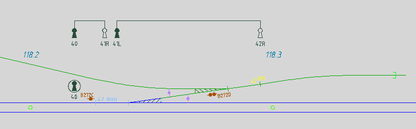
Illus.: Representation of Key dependencies in the drawing
In the PlanPro glossary, the objects are formulated as follows:
Key release instrument
Electromagnetic component which checks the presence of a key, holds it and has an interlocking station logic dependency.
Key release instruments are used to hold or release keys, which are usually used to make other elements controllable. In individual cases, key release instruments serve only as key switches.
The Representation in the layout plan occurs at the place of operation (e.g. Interlocking station, Other building), which is described by the accommodation. There is no representation on or near the track!
DB Rules and Regulations: Representation by drawing in the layout plan according to 819.9002 2.
Lock Combination
Mechanical device for releasing several (dependent) Keys by one (main) Key.
The main key is held as long as at least one bolt of the dependent locks is extended. Generally, resetting consists of removing the main key and locking the dependent keys.
DB Rules and Regulations: Representation through drawing in the layout plan. There is no current Ril existing, old drawing standards are used.
Lock
Mechanical component which, by locking or unlocking a key, allows a bolt to be extended or retracted or closes or opens an electrical contact.
Depending on the locked element, the corresponding Attribute Group is selected:
•Level crossing,
•Derailer,
•Lock combination,
•Special system (e.g. movable bridge),
•Key release instrument,
•Switch.
DB Rules and Regulations: The layout plan shows according to 819.9002 3:
•Locks with a symbol (e.g. Key release instrument) or additional information to other symbols (e.g. Switch);
•Dependencies through a drawing with repeated representation of the lock positions as filled or empty keyhole.
Key
Safety-related element for the production of Key dependencies over locks on elements.
The Key in the safety-related sense is a representative and unique object within a locality. By possessing the key, a certain system condition can be safely and unambiguously inferred. Thus secure dependencies can be created by connection with further route-related interlocking elements or an information processing system.
As a rule, there are always two equally closing locks locally, and rarely more. If a key release instrument is only used as a switch (e.g. to lock track routes), there is only one key for each lock.
There are 24 different key bit shapes, which are combined with six key groups. Not every key bit is combined with every group. A total of 92 different key forms are available.
DB Rules and Regulations: The Planning of Key forms is not yet part of PT1. For the forms, Standard drawings exist.
(Source: PlanPro Glossary)
Procedure:
1.The Insertion of an Accommodation of the type Schaltschrank/Schaltkasten can be performed with the function 'Accommodation'.
Command Line: PRS_SSP_UNTERBRINGUNG
Ribbon: ProSig EPU -> Equipment SCT -> Key Dependencies -> Accommodation
oThe Description for inserting an accommodation is found under Creating Accommodations, Step 2.
oThe Accommodation is a Dot-like PSO and is stored on the layer PRS-ACCOMMODATION.
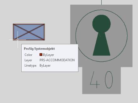
Illus: Representation of an Accommodation of the type 'Schaltschrank/Schaltkasten'
| for the enclosure of a key release instrument in the drawing |
oWhen creating the accommodation, the type 'Schaltschrank/Schaltkasten' (A) with associated mounting 'Pfosten' (B) is preset as default value.
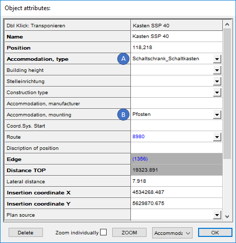
Illus.: Attributes of an Accommodation of the type 'Schaltschrank/Schaltkasten'
2.Insert dependent object(s) (Key release instrument, Switch, derailer, Level crossing protection system, Lock combination) for which a Key dependency should be created.
oKey release instruments can be inserted using the function 'Key Release Instrument'.
Command Line: PRS_SSP_EINF
Ribbon: ProSig EPU -> Equipment SCT -> Key Dependencies -> Key Release Instrument
oLock combinations can be inserted using the function 'Lock Combination'.
Command Line: PRS_SCHLOSSKOMBI_EINF
Ribbon: ProSig EPU -> Equipment SCT -> Key Dependencies -> Lock Combination
3.Insert lock or locks using the function 'Lock' ( represented according to Ril 819.9002 3).
Command Line: PRS_SCHLOSS_EINF
Ribbon: ProSig EPU -> Equipment SCT -> Key Dependencies -> Lock
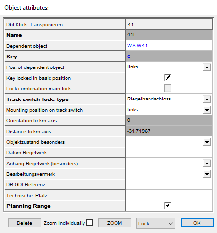
Illus.: Object Attributes of a Lock
4.For the inserted lock or locks, assign the dependent objects inserted under 1 (key release instrument, switch, derailer, level crossing protection system, lock combination):
oUsing the function Edit Object(s) for the attribute 'Dependent object' in the value field, use the drop-down list to select the corresponding object based on its name or
oRight-click with the mouse in the value field of the attribute 'Dependent object' to open the context menu. The corresponding object in the drawing can be selected via the menu item 'Assign object(s)'.
oHints: For Switches, the Switch component should be specified as a Dependent object.
5.Create key with the function 'Key'.
Command Line: KEY_CREATE
Ribbon: ProSig EPU -> Equipment SCT -> Key Dependencies -> Key
6.Subsequently, the Key bit and Group can be assigned to the newly created Key via the Attributes.
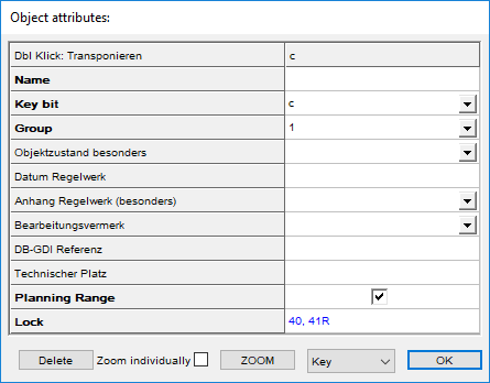
Illus.: Object Attributes of a Key
Hints
•More than two locks can also be assigned to one key.
•For a representation as shown in the following illustration, it is necessary to insert a lock with an overlying cover under the key release instrument.
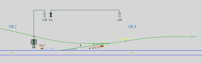
Illus.: Representation of Key dependencies in the drawing with direct connection from Lock to Key Release Instrument