Example: Inserting a Multi-Section Shunting Signals

Contents
Process:
•Inserting a Multi-section shunting signal using the example 60ZU22 with Zs3, Zs3v, Zs7 and marker light.
Requirements:
•see Signals - EPU
Description:
The Procedure for creating a multi-section shunting signal is explained step by step using the example 60ZU22.
After inserting and editing the signal attributes in the 'Signal' dialog area, the corresponding Signal aspect of the screens and the signal type indicator are generated automatically. For the frame 'Schirm', the signal aspects for substitute signal (Zs7) and marker light are also added. A separate signal frame is created for the designation plate and for the signal aspects speed indicator at signal (Zs3) and pre-speed announcer at signal (Zs3v). For the signal, the signal mount 'Fundament' is created.
It is described which attributes are to be edited, in order to realize a correct view in the drawing and to ensure (at a later time) a complete export.
Supporting video sequence:
Beispiel_Einfuegen_eines_Mehrabschnittssperrsignals.mp4 (Size: 14,5 MB)
Procedure:
1.With the button 'New' (A) a new signal can be inserted, as described under Insertion of Signals. To edit this example, select the signal type 'Leer'.
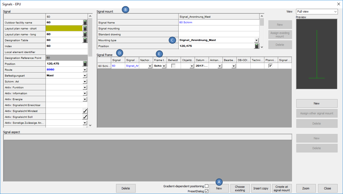
Illus.: Newly inserted Signal
oWhen inserting, select a point on the topological edge.
oThe Signal is generated with a Signal mount (B) ('Mounting type' (C) = 'Signalanordnung Mast') and an empty Signal frame (D) ('Frame type' (E) = 'Schirm').
2.The following attributes have to be edited in the area Signal (F):
Nr. |
Attribute |
Value |
1 |
Local element identifier |
ZU22 |
2 |
Befestigungsart |
Mast |
3 |
Schirm: Bedienart |
Wb/zb |
4 |
Schirm: Art |
Mehrabschnittssperrsignal |
5 |
Aktiv: Funktion |
Zwischensignal |
6 |
Aktiv: Information |
P-Hausen (Objekt Außenelementansteuerung) |
7 |
Aktiv: Energie |
P-Hausen (Objekt Außenelementansteuerung) |
8 |
Schirm: Dunkelschaltung |
nein (Strich) |
9 |
Schirm: Richtpunktentfernung |
272 |
10 |
Schirm: Signalsystem |
Ks |
11 |
Aktiv: Signalsicht Erreichbar |
500 |
12 |
Aktiv: Signalsicht Mindest |
300 |
13 |
Aktiv: Signalsicht Soll |
500 |
14 |
Schirm: Streuscheibe |
HG |
15 |
Schirm: Betriebsstellung |
HG4 |
Table: Attributes to be edited in the section Signal
oFor the allocation of the attributes 'Aktiv: Information' (6) and 'Aktiv: Energie' (7), it is first necessary to Create the External Control Architecture.
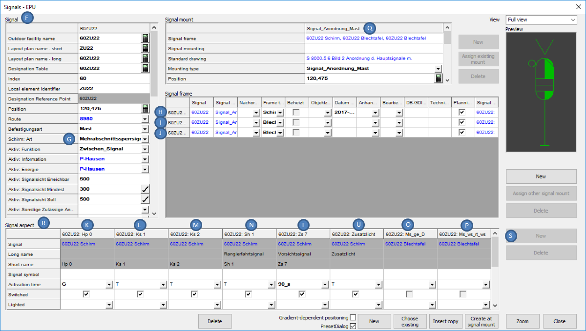
Illus.: Editing the Attributes for the Screen and the Signal Type Indicators
oAfter changing the attribute 'Schirm: Art' (G), the corresponding signal aspects are automatically created.
▪The Signal aspect IDs of the main screen (Signal aspect IDs = 'Hp_0' (K), 'Ks_1' (L), 'Ks_2' (M) and 'Sh_1' (N)) are assigned to the frame with the 'Frame type' = 'Schirm' (H).
▪For the Signal type indicator (Signal aspect IDs = 'Ms_ws_rt_ws' (O) and 'Ms_ge_D' (P)) separate frames with the frame type 'Blechtafel' (I, J) are created. To each signal frame 'Blechtafel' a signal aspect object with the corresponding 'Signal aspect ID' is assigned.
3.For the automatically created Signal mount (Q) the following attributes have to be edited:
Nr. |
Attribute |
Value |
1 |
Standard drawing |
S 8000.5.6, Bild= 2 (Objekt Regelzeichnung) |
2 |
Mounting type (Check value) |
Signalanordnung Mast |
3 |
Obere Lichtpunkthöhe |
5.400 (Angabe in Metern, Dezimaltrenner ".") |
Table: Attributes to be processed for Signal Mount
oFor the allocation of the attribute 'Standard drawing' (1), first Create a corresponding Standard Drawing.
4.To define the switch-ability of the signal aspects for the screen, after marking the frame 'Schirm' (H) in the area Signal aspect (R), the following attributes have to be edited for the assigned signal aspects:
Nr. |
Signal aspect ID |
Lighted |
Switched |
Activation time |
Signal symbol |
1 |
Hp_0 |
leer |
ja |
G |
leer |
2 |
Ks_1 |
leer |
ja |
T |
leer |
3 |
Ks_2 |
leer |
ja |
T |
leer |
4 |
Sh_1 |
leer |
ja |
T |
leer |
Table: Attributes to be edited for the existing Signal aspects of the Signal frame Screen
5.For the marked Frame type= 'Schirm' (H) the signal aspects for the Vorsichtsignal (T) and the Zusatzlicht (U) have to be applied one after the other with the button 'New' (S) in the area Signal aspect (R):
Nr. |
Signal aspect ID |
Lighted |
Switched |
Activation time |
Signal symbol |
1 |
Zs_7 |
leer |
ja |
90 s |
leer |
2 |
Zl_o |
leer |
ja |
T |
leer |
Table: Creating Signal aspects for the Signal frame Screen
6.After marking a signal frame 'Blechtafel' (I, J) the following attributes have to be edited in the area Signal aspect (R) one after the other for the respectively assigned signal aspect (O, P):
Nr. |
Signal aspect ID |
Lighted |
Switched |
Activation time |
Signal symbol |
1 |
Ms_ws_rt_ws |
leer |
leer |
leer |
leer |
2 |
Ms_ge_D |
leer |
leer |
leer |
leer |
Table: Attributes to be edited for the Signal frame Metal board (Signal type indicator)
7.To create a new signal frame for the Bezeichnungsschild (V), first mark the signal mount with the 'Mounting type' = 'Signalanordnung Mast' (AI). Then in the area 'Signal frame' with the button 'New' (Y) a new frame will be created.
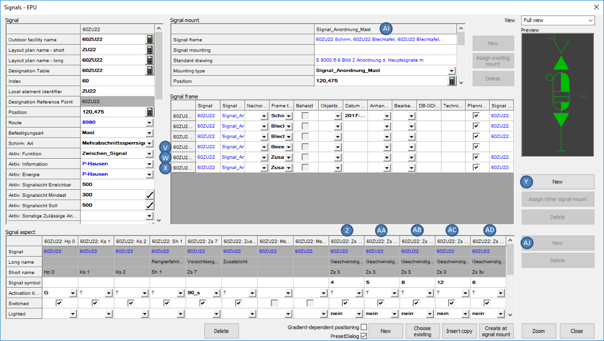
Illus.: Editing the Attributes for the Designation plate, Speed indicator at signal and Pre-speed announcer at signal
The following attribute should be adjusted:
Nr. |
Attribute |
Value |
1 |
Frame type |
Bezeichnungsschild |
Table: Attributes to be edited for the newly created Frame Designation plate
oFor the designation plate, no signal terms are created.
8.To plan Zs 3 at signal ZU22 (W), first mark the signal mount with the 'Mounting type' = 'Signalanordnung Mast' (AI). Then, in the area 'Signal frame', create a new frame with the button 'New' (Y). The following attribute needs to be adjusted:
Nr. |
Attribute |
Value |
1 |
Frame type |
Zusatzanzeiger |
Table: Attribute to be edited for the newly created Signal Frame
9.After marking the new signal frame 'Zusatzanzeiger' (W) in the area 'Signal frame', with the button 'New' (AJ) the following signal aspects for Zs 3 have to be created one after the other (Z, AA, AB, AC):
Nr. |
Signal aspect ID |
Lighted |
Switched |
Activation time |
Signal symbol |
1 |
Zs_3 |
nicht beleuchtet |
ja |
T |
4 |
2 |
Zs_3 |
nicht beleuchtet |
ja |
T |
5 |
3 |
Zs_3 |
nicht beleuchtet |
ja |
T |
8 |
4 |
Zs_3 |
nicht beleuchtet |
ja |
T |
12 |
Table: Creating Signal Terms for the Frame Auxiliary indicator (Zs3)
10.To plan the Zs 3v at signal ZU22 (X), first mark the signal mounting with the 'Mounting type' = 'Signalanordnung Mast' (Q). Then, in the area 'Signal frame', create a new frame with the button 'New' (Y). The following attribute needs to be adjusted:
Nr. |
Attribute |
Value |
1 |
Rahmenart |
Zusatzanzeiger |
Table: Attribute to be edited for the newly created Frame
11.After marking the new frame 'Zusatzanzeiger' (X) in the area 'Frame', the button 'New' (AJ) is used to create the following signal aspect for Zs 3v (AD):
Nr. |
Signal aspect ID |
Lighted |
Switched |
Activation time |
Signal symbol |
1 |
Zs_3v |
nicht beleuchtet |
ja |
T |
6 |
Table: Creating Signal aspects for the Frame Auxiliary indicator (Zs3v)
12.In order to construct the Foundation, first select the signal mounting with the 'Mounting type' = 'Signalanordnung Mast' (AK). Then, use the button 'New' (AF) to create a new signal mounting for the Fundament (AE).
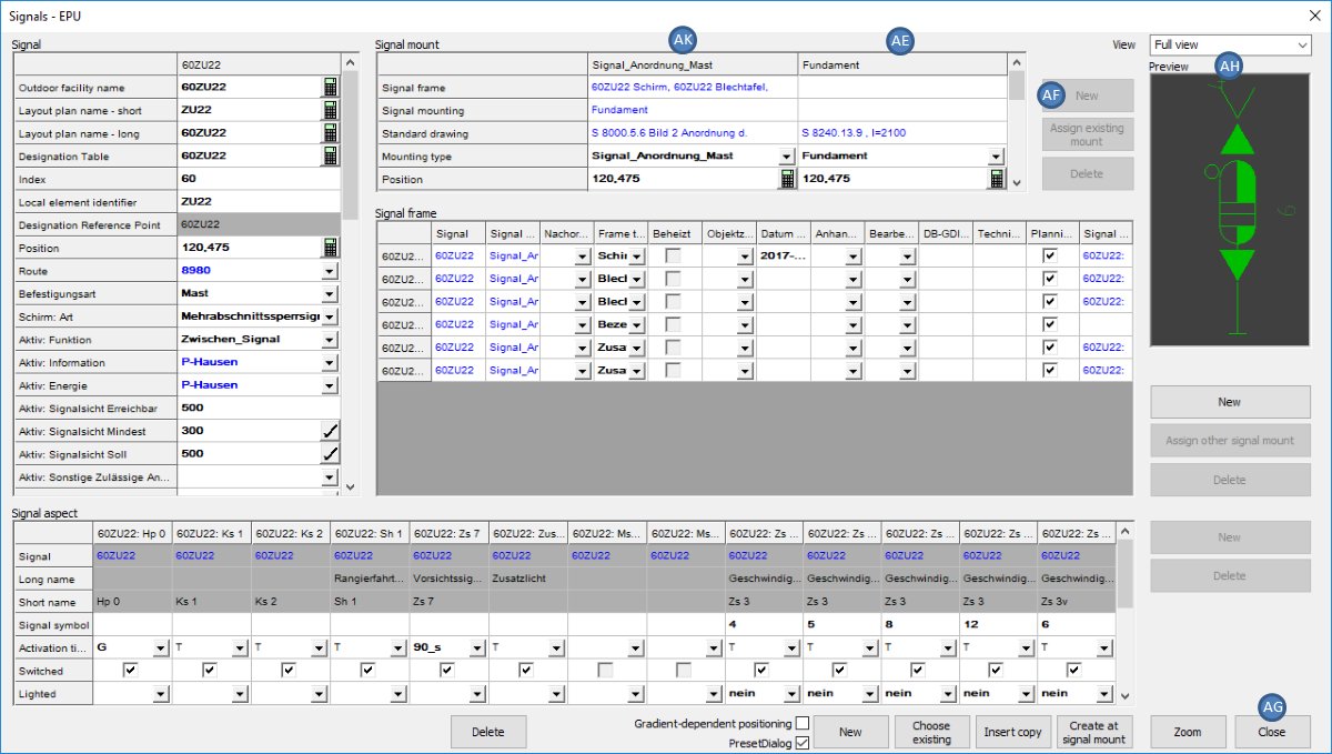
Illus.: Creating the Signal Mount Fundament
For the Signal mount 'Fundament' (AE) the following attributes have to be edited:
Nr. |
Attribute |
Value |
1 |
Befestigungsart |
Fundament |
2 |
Regelzeichnung |
S 8240.13.9 , l= 2100 (Objekt Regelzeichnung) |
3 |
Höhe Fundamentoberkante |
-0.100 |
Table: Attributes to be edited for the newly created Signal mount Fundament
oFor the allocation of the attribute 'Standard drawing' (2), it is first necessary to Create a corresponding Standard Drawing.
13.The button 'Close' (AG) will close the dialog and the signal is displayed in the drawing.
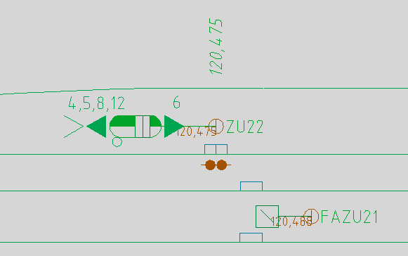
Illus.: Signal 60ZU22 in the drawing