Creating Switching Device(s) with the EPU Object Inserter

Contents
Process:
•Creating Switching Device(s) with the EPU-Object Inserter.
Requirements:
•Creating Level Crossing Activations
•Inserting FMA Components and Track Clearance Sections
Description:
In ProSig, a switching device is a logical object that is used for the selective activation of switching processes, e.g. in Level crossing protection system or at Shunt- and Gravity hump system.
Switching devices are often separate train controls (e.g. wheel detectors), but also Track clearance sections or Axle counter can be used for the purpose of a switching device(s) (double utilization).
The Descriptions for inserting switching device(s) using special functions can also be found on the Level crossings - Dependencies and Activations, Step 3 and Planning the Block Systems, Step 12 pages.
In the PlanPro glossary, the object is formulated as follows:
Switching Device (Schaltmittel_Zuordnung)
Assignment object for selective activation of Switching Operations.
Example: Level crossing protection system, Shunt- and Gravity hump system.
Switching devices are often separate train controls (e.g. wheel detectors), but track clearance sections or Axle counter (FMA Components) can also be used for the purpose of a switching device (double utilization). A switching device, however can be used for different functions. The assignment object Switching Device captures a specific request (Reference, which is directed to the requesting object, e.g. Level crossing ON, Level crossing OFF, Close Track Route) and assigns this function to a specific system (Train control, Track clearance section or Axle counter) as well as a description of this system in the Signalling layout plan.
The Function 'Track route closure (Requester = Track Path of a Track Route)' is intended for closure of main routes. Other applications are currently not included in the model.
The Reference to the request is not required if the assignment is clearly derived from the topology (example: separate switching device for the function 'Zweites Haltfallkriterium'). In this case, only the reference to the system and the labeling in the layout plan are given.
(Source: PlanPro Glossary)
Procedure:
1.The Creation of a Switching Device(s) can be performed with the function EPU-Object Inserter. Select the Object type 'Switching Device(s)'.
Command Line: PRS_EPU_EINF
Ribbon: ProSig EPU -> Equipment SCT-> EPU-Object Inserter
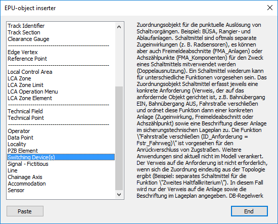
Illus.: Selection of the object type Switching Device in the EPU Object-Inserter
2.With the button 'Paste' a new object 'Switching Device' can be created. The Switching Device is a logical object and is not displayed in the drawing.
3.After creating the Switching Device(s), all relevant data should be entered. The object attributes can be edited later using the Edit Object Type function.
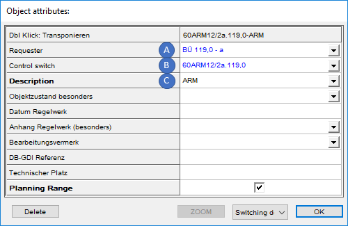
Illus.: Object attributes of a Switching Device(s) using ARM as an example
(Response message for Level crossing protection system)
oThe 'Requester' attribute (A) is used to specify the object that makes a switching request (e.g. a Level Crossing Activation).
oThe 'Control Switch' attribute (B) must be used to specify the object that serves a switching request. The linked object can be a Track clearance section, an FMA component or a Sensor.
oThe 'Description' attribute (C) is used to mark the functionality of the switching device(s). The following values are available:
▪ARM
▪Ein
▪ZL_Anstoss
▪Haltfall
▪Awanst