Track Routes

Contents
Process:
•Planning of Main Routes and Shunt Routes
•Displaying and editing the Signalling for a Track route
•Mapping concatenated Main routes or Shunt routes
•Assignment of Flank Protection Measures to the Shunt Route
Requirements:
see Track Paths, Overlaps, Track Routes and Flank Protection
Description:
The Track route in ProSig is a logical object and represents the secured path for a train move or shunt move. After creating a track route with the Track route editor, it is possible to specify the track route type (main or shunt route) via the object attributes.
Each track route has a traveled part (Track path). An overlap can be assigned to a track route. For the track routes with several overlaps, several main routes are created, which are based on the same part of the main route. A track route can contain a flank protection section.
The Track route editor can be used to plan both the Signalling to a track route and track route series and the assignment of flank protection measures to the shunt route.
In the PlanPro glossary, the object is formulated as follows:
Track Route (Fstr_Zug_Rangier)
Main route and Shunt route.
Each main route is assigned to an overlap (modeled in Fstr DWeg). If there are track routes with several overlaps, several main routes will be created, which are based on the same part of the main route (modeled in Fstr Fahrweg).
The Data model is also used to plan Centralized block track routes. The associated distance to danger point is mapped to Fstr DWeg. A Centralized block track route (Attribute 'Type' = Zug Zentralblock) over the CBI-Central Unit-Limit is planned in two sub block track routes (Attribute 'Type' = Zug Zentralblock) in the area of the respective CBI Central unit. Thereby a part of the length zero can occur, if the second sub block track route consists of the overlap only. The target signal of the first is the start signal of the second sub block track route.
Track routes across a CBI-Central Unit-Limit (FAP) are planned as two sub routes (Attribute 'Type' = Zug Teil /Zug Teil Umfahr /Rangier Teil / Rangier Teil Umfahr). When the first sub route is continued with several further sub routes, a separate instance of the first sub route needs to be created for each planned combination (analogous to the assignment of several overlaps). The link to the second sub route is established via the attribute 'Folgeabhängig' of the track route.
A Track route center switch section has no overlap. The track route center switch section is not explicitly linked to each other and also not to the main route, as this is determined by the topology and especially by the start and destination.
A Shunt route also doesn't have overlap.
The special attributes of main route/shunt route/track route center switch section are stored in their own attribute groups which are mutually exclusive.
Group exits are mapped as main routes without special attributes. The group exit signal is explicitly specified via the attribute 'Group exit signal', thus the group exit track route is uniquely identifiable.
DB Rules and Regulations:
•Table of main routes (one row),
•Table of shunt routes (one row),
•Middle switch track section table (one row).
(Source: PlanPro Glossary)
Supporting video sequence:
Erstellung_Fahrstrasse.mp4 (Size: 11,0 MB)
Procedure:
1.To Create a Track route, select the sub-tab 'Create' on the main tab 'Track routes'.
To Display and edit the Signals for an existing track route, continue with Step 7.
To Assign an existing main or shunt routes to the Track route series continue with Step 15.
For the Assignment of flank protection measures to shunt routes continue with Step 22.
Command Line: PRS_FAHRSTRASSE
Ribbbon: ProSig EPU -> Equipment SCT -> Track Routes

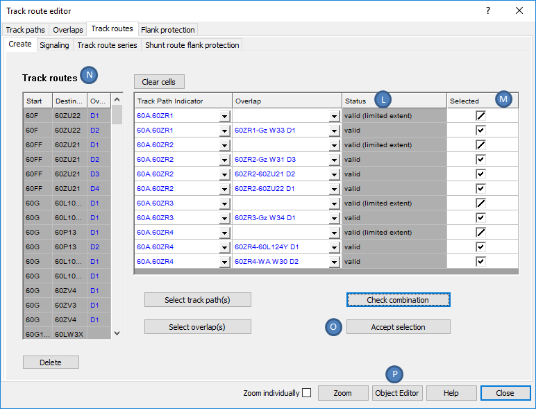
Illus.: Create Track routes with unchecked Status
oIf track routes already exist in the Planning project, they are displayed in the list of 'Track routes' (F). If no track routes are created yet, the List (F) will be empty.
oAfter selecting an object in the list (F), it is possible to display and edit the attributes of the selected object via the button 'Object Editor' (AW). If several track routes have been selected in the List (F), the object attributes of all selected objects are displayed simultaneously.
oIf linked objects are marked in the list (G) (columns 'Track Path Indicator', 'Overlap'), the object attributes of these objects can be displayed with the button 'Object Editor' (AW).
oAfter selecting objects in the list (F), use the button 'Zoom' (AV) to select and zoom these objects in the drawing. The zoom can be done individually or together, depending on the setting of the check box 'Zoom individually' (AU).
oIf linked objects are marked in the List (G) (columns 'Track path Indicator', 'Overlap'), using the button 'Zoom' (AV) the objects in the drawing can be selected and zoomed. The Zoom can be done individually or together, depending on the setting of the check box 'Zoom individually' (AU).
2.The Button 'Select track path(s)' (H) is used to select a track path in the drawing for the track route being created. When selecting, either a track path or the start signal of a track path can be selected.
oTo create multiple track routes simultaneously, it is possible to select multiple track paths or start signals from track path. Non-relevant objects are filtered out during selection.
oWhen the dialog is reopened, the selected track paths are displayed in the list of possible Start- / Destination combinations (G) under the attribute 'Track Path Indicator' (B). By clicking the button 'Select track path(s)' (H) again, further track paths can be added to the existing selection.
3.The Button 'Select overlap(s)' (I) is used to select an Overlap in the drawing for the track route being created.
oIf several track routes are created at the same time, several overlaps can also be selected. During selection, non-relevant objects are filtered out.
oWhen the dialog is reopened, the selected overlaps are displayed in the List of possible Start- / Destination combinations (G) under the attribute 'Overlap' (C). By clicking the button 'Select overlap(s)' (I) again, further overlaps can be added to the existing selection.
oThe Attribute 'Status' (D) of the possible Start- / Destination combinations is still 'unchecked'.
oThe Attribute 'Selected' (E) of the possible Start- / Destination combinations is not yet assigned.
4.With the button 'Check combination' (J), all possible Start- / Destination combinations in List (G) are automatically checked for validation.
Illus.: Track routes to be created, checked
oThe Attribute 'Status' (L) changes from 'unchecked' to one of the following statuses:
Status |
Significance |
|---|---|
valid |
valid Track route |
valid (limited extent) |
The Validation of the track route cannot be unambiguously assigned by the algorithm and subsequently it needs to be checked manually by the planner (e.g. if the track route is considered as a shunt route, no overlap should be specified). If no overlap is specified, the track route is assigned to the status 'valid (limited extent)') |
valid shunting route only |
valid Shunting route (without Overlap) |
invalid |
invalid Track route |
present |
Track route already exists in the project |
Table: List of statuses and their significance for the Validation of Track routes
oValid Track routes and Shunt routes are automatically selected (M). Existing or invalid track routes are automatically deselected.
oRestricted valid track routes which should be included in the project have to be selected separately.
oExisting track routes, that should be imported into the project again, have to be selected separately (if both a shunt and a main route can be created with the same track path).
oTrack routes or Shunt routes that are valid, but that should not be included in the project and should be deselected.
5.With the button 'Accept selection' (O) the selected track routes are created.
oThe Name of the track route consists of the name of the track path and the name of the assigned overlap and it is displayed in the list (N).
oTrack routes are logical objects and are not represented graphically in the drawing.
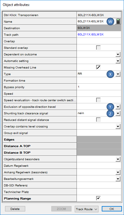
6.After selecting a track route in the list (N), the button 'Object Editor' (P) can be used to display the object attributes of the track route. If several track routes are selected in the list (N), the object attributes of all selected objects are displayed simultaneously.
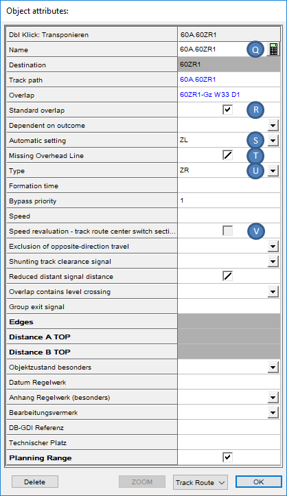 |
 |
Illus.: Object attributes of a Main route |
Illus.: Object attributes of a Shunt route |
oThe Attribute 'Standard overlap' (R) is evaluated for the table of overlaps. This overlap is then considered the first entered overlap for each signal.
oThe Attribute 'Automatic setting' (S) corresponds to column 9 'Fleeting/train control' of the table of main routes.
oThe Attribute 'Missing Overhead Line (T) corresponds to column 7 'Railway route in areas without overhead structures' of the table of main routes.
oThe Attribute 'Type' (U, X) is evaluated for column 2 'Type' of the table of main routes or table of shunt routes. After setting the track route type, the Name of the Track route or Shunt route (Q, W) can be automatically corrected using the corresponding button with the calculator symbol.
oThe Attribute 'Speed revaluation - track route center switch section' (V) corresponds to column 5 'Speed revaluation' of the Middle switch track section table.
oThe Attribute 'Exclusion of opposite-direction travel' (Y) corresponds to column 9 'Exclusion of oncoming movement' of the table of shunt routes.
oThe Attribute 'Shunting track clearance signal' (Z) corresponds to column 10 'Track clearance point verification' and column 13 'Verification of destination track clearance dispensed with' of the table of shunt routes.
7.To Display and Edit the Signaling for an existing track route, select the sub-tab 'Signaling' on the main tab 'Track routes'.
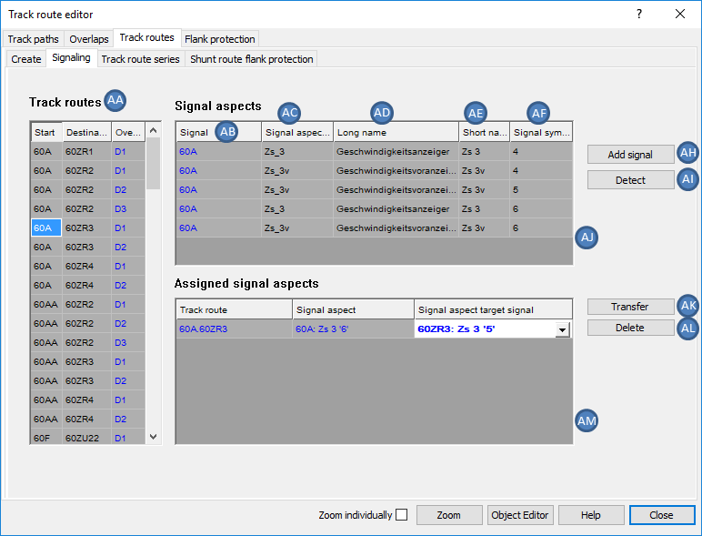
Illus.: Signaling for Track route A.ZR3 D1
8.In the list of Track routes (AA), select the Track route for which the signals are displayed or edited.
oIn the list (AJ), the signal aspects of the start signal of the track route are displayed.
oIn the column 'Signal' (AB), the name of the start signal of the track route is displayed.
oIn the column 'Signal aspect ID' (AC), the ID of the Signal aspect is displayed.
oIn the column 'Long name' (AD), the long name of the Signal aspect according to Ril. 301 (Signalling regulation and rule book).
oIn the column 'Short name' (AE), the short name of the Signal aspect according to Ril. 301 (Signalling regulation and rule book).
oIn the column 'Signal symbol' (AF) for Signal aspects that can display Signal symbols, in each case one Signal symbol is displayed.
9.To edit a Signal aspect, it is necessary to mark it in the list (AJ). It is also possible to select and edit several Signal aspects simultaneously.
10.The Button 'Add signal' (AH) can be used to select signals in the drawing which have Signal aspects that influence the course of the track route. Confirm the selection with the Enter key or by clicking in the drawing. Example: Distant signals with Pre-speed announcer at signal.
11.In the list (AM), all the Signal aspects are listed which receive a special setting for the current route (Signaling special). With the button 'Transfer' (AK) a marked Signal aspect can be transferred manually to the List (AM).
oFor a direction indicator it is necessary to transfer the clear aspect which has to be set for this route.
oOn shunt routes: Transfer of the shunting aspects SH1 for the shunting signals, that have to be set to marker light for this route.
12.With the button 'Detect' (AI), the Signal aspects which receive a special setting for the current route (Signaling special) can be automatically transferred to the List (AM). Subsequently, the aspects have to be checked and corrected if necessary.
13.With the button 'Delete' (AL), it is possible to remove Signal aspects from the List (AM). The deleted Signal aspects are retained in the project.
14.To Assign an existing main or shunt routes to the Track route series, select the sub-tab on the main tab 'Track routes'.
To Create main routes and shunt routes in a series, continue with Step 15.
To Remove a track route from the assignment to a series of main routes and shunt routes, continue with Step 20.
To Delete an existing Track route series, continue with Step 21.
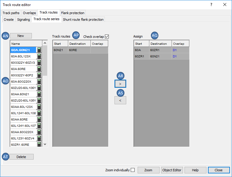
Illus.: Creation of the Track route series 60A.60N21
15.With the button 'New' (AN) a new, empty field is created in the list of Track route series (AO).
oThe newly created field is inserted at the beginning of the Track route series (AO) List.
oThe Name of the track route series is automatically determined by the selection of the routes, see Step 19.
16.After selecting the newly created field in the Track route series (AO) list, select a track route from the existing Track routes (AP) list that should be assigned to the Track route series.
oThe Overlap for main routes is defined by selecting the previous track route. If several overlaps have to be specified for an aligned main route, the adjacent main route has to be created as often as necessary, each time with a different overlap.
17.The Button '>' (AR) is used to transfer the selected track route from the list 'Track routes' (AP) to the list 'Assign' (AQ).
oSubsequently, only the routes whose start signal corresponds to the destination signal of the last assigned track route are displayed in the List (AP).
18.Repeat Step 16 and Step 17 till the end of the track route is reached.
19.For the marked field in list (AO), the name of the Track route series is automatically updated after assigning the selected track routes to the Track route series via the button '>' (AR).
20.The Assignment of track routes to a track route series can be removed. Proceed as follows:
oSelect the track route in the list (AO), for which the assignments need to be changed.
oSelect one or more track routes in the list (AQ), for which the assignments to the selected track route should be removed.
oRemove the assignments with the button '<' (AS).
21.After marking one or more adjacent track routes in the list (AO), they can be deleted with the button 'Delete' (AT).
22.To Assign flank protection measures to the shunting route, select the sub-tab 'Shunt route flank protection' on the main tab 'Track routes' .
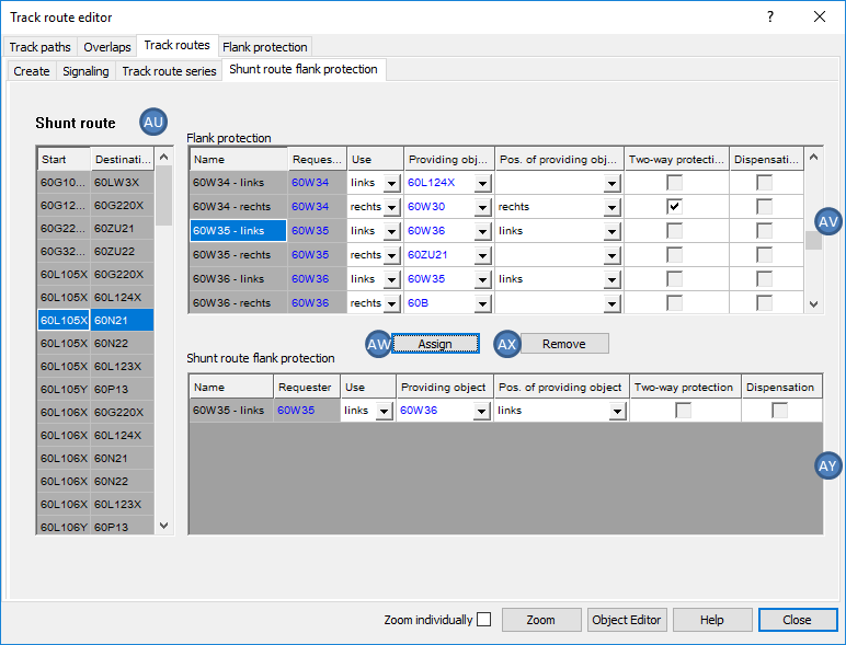
Illus.: Assignment of flank protection measures to shunting route 60L105X-60N21
oThe Pre-requisite for the assignment of flank protection measures to a shunting route is the creation of flank protection objects. For information on creating the flank protection objects, see also Flank Protection, Step 1. If no flank protection objects are created yet, then the list 'Flank protection' (AV) is empty.
23.In the list 'Shunt route' (AU), select the shunt route for which a flank protection measure from the list (AV) should be assigned.
24.After selecting a corresponding flank protection object in the List (AV), the flank protection measure is transferred to the list 'Shunt route flank protection' (AY) via the button 'Assign' (AW) and assigned to the previously marked shunting route.
25.The Assignment of flank protection measures to a shunt route can be removed. Proceed as follows:
oSelect the shunt route in the list (AU) for which the assignments should be changed.
oSelect one or more flank protection objects in the list (AY) for which the assignments to the selected shunt route should be removed.
oRemove the assignments with the button 'Remove' (AX).