Planning the Block Systems

Contents
Process:
Edit and display the technical information of the Block technique relevant for the project:
•Defining Route Destinations
•Projecting of the Block Systems
Requirements:
•Specifying Track Identifiers for Section Tracks
Description:
The Block systems are planned in ProSig using the logical objects Block system, Block element and Block route.
In the PlanPro glossary, the objects are formulated as follows:
Block System
Technical equipment for the block technical protection of train movements on section tracks.
The corresponding designation of the section tracks are determined by the object track identifier (Attribute 'Track'). The parentheses of the track identifier for section track are part of the track identifier.
For the representation of the track data for a Block route, the object Block route is used through the object Block element (Attributes 'Point of start operation' or 'Duplex transmission location').
If Line block system is planned, a block system is assigned to a section track. In the case of a bidirectional track, where both section tracks are equipped with line block system, each section track is assigned its own block system. A Block system has two block elements A and B (block instruments), which are assigned according to the direction of travel. For single-track lines, the direction A - B results from the Line Chainage. An exception is the one train working (OTW), to which only one block element is assigned.
The name Block is also used as a summary of all objects.
Block Element
Element at the end of a Block route/Block system.
A Section track, which is equipped with a block system, has two corresponding block elements in the adjacent operation control post. One exception is the one train working (OTW), which has only one block element.
The Block element also refers to the associated Block route, which contains the relevant block technical and operational data of the route. With bidirectional track, two block elements refer to the block route.
The Block element refers to a signal in the form of a route destination (A-field) (Attribute 'Virtual outbound destination') and to a switching device for clearance inspection (E-field) (Attribute 'clearance inspection').
If a separate end-of-train signal is used, the attribute 'End-of-train signal' refers to a corresponding operating unit.
The Block construction (Attribute 'Construction') of the respective terminal can be used to identify the type of technical implementation.
Block Line
Saving the operationally relevant track data of a Block route.
The object contains the typical operational information (Track data) between two register stations for information purposes. It is assigned to the block element of the associated block post.
(Source: PlanPro Glossary)
Procedure:
1.Before the creation of block systems with the Block systems editor, the exit destinations for the current area of planning and consideration have to be defined. In ProSig the exit destinations (operating destinations) are displayed as virtual signals with the operational function 'ZZS (Zug-Ziel Strecke)'.
Start EPU-Object Inserter and select object type 'Signal - Fictitious'. Information on inserting and editing fictitious signals can be found under the process Signals - Fictitious.
Command Line: PRS_EPU_EINF
Ribbon: ProSig EPU -> Equipment SCT -> EPU-Object Inserter
oFor the neighboring district, the exit destinations are inserted on the topological edge at the end of considered range.
2.After the insertion, all relevant data should be entered via the function Edit Object(s).
Command Line: OE
Ribbon: ProSig EPU -> Tools -> Edit Object(s)
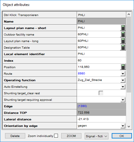
Illus.: Object attributes of an Exit Destination
oFor the Attribute 'Local element identifier', the designation of the exit destination should be specified as the value.
oFor the Attribute 'Operating function' the value 'ZZS (Zug-Ziel Strecke)' should be selected.
3.To Create and Edit the Block systems, start the Block systems editor.
Command Line: PRS_BLOCK
Ribbon: ProSig EPU -> Equipment SCT -> Block Systems
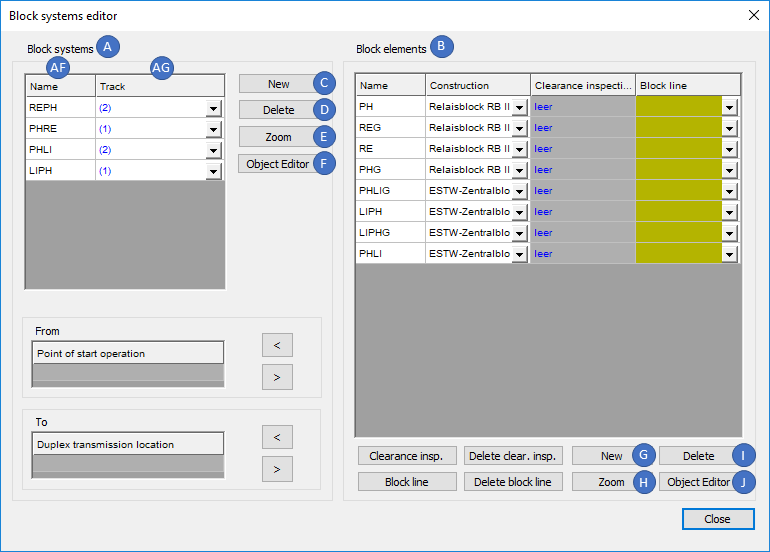
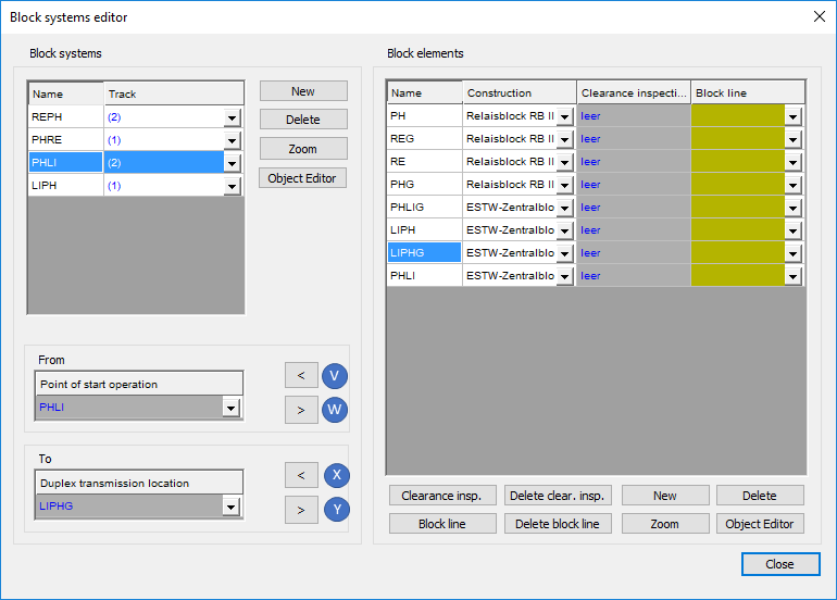
Illus.: Dialog Block systems editor
4.The Creation of a Block system can be performed with the button 'New' (C).
oThe prompt 'Gleis(e) wählen:' is displayed - When creating, select the track identifier for the track section between the two block instruments (Point of start operation / Duplex transmission location). The selected track identifier is then displayed in the attribute 'Track' (AG).
oThe Block system is then displayed in the list 'Block systems' (A). The attribute 'Name' (AF) can be used to define a name for the block system.
oThe Block system is a logical object. After marking a block system in the list (A), the associated track identifier is zoomed with the button 'Zoom' (E).
oThe Button 'Delete' (D) can be used to delete an existing block system from the project.
5.The Attributes of the Block system can be edited using the button 'Object Editor' (F) or after closing the block systems editor by using the function Edit Object(s).
Command Line: OE
Ribbon: ProSig EPU -> Tools -> Edit Object(s)
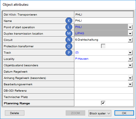
Illus.: Attributes of a Block System
oFor the Attribute 'Name' (K), the name for the block system is entered.
oAt first, the attributes 'Point of start operation' (L) and 'Duplex transmission location' (M) are not assigned. For the assignment of the block elements to a block system see also Step 8 and 9. Then the names of the block elements are included in the mentioned attributes.
oThe Attribute 'Circuit' (N) indicates the execution of the circuit for the transmission of the block information.
oThe Attribute 'Protection transformer' (O) can be used to determine whether the circuit of the line block system is equipped with protection transformers.
oThe Attribute 'Track' (P) is automatically assigned to the track identifier selected when creating the block system.
6.The Creation of a Block elements can be performed with the button 'New' (G).
oThe prompt 'Bedienpunkt(e) wählen:' appears - While creating, one or more fictitious signals from Step 1 can be selected in the drawing. For each selected fictitious signal a corresponding block element is created in the List (B).
oThe Block elements are then displayed in the list 'Block elements' (B). The name of a block element is automatically taken from the name of the corresponding fictitious signal.
oThe Block element is a logical object. After marking a block element in the list (B), the corresponding fictitious signal is zoomed with the button 'Zoom' (H).
oWith the button 'Delete' (I) an existing block element can be deleted from the project. After deleting a block element, the entries for the Point of start operation and Duplex transmission location of the block system are also deleted.
7.The Attributes of the block element can be edited with the button 'Object Editor' (J) or after closing the block systems editor by using the function Edit Object(s).
Command Line: OE
Ribbon: ProSig EPU -> Tools -> Edit Object(s)
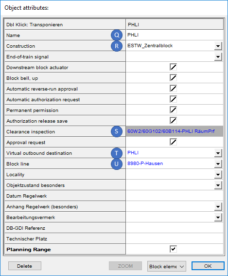
Illus.: Attributes of a Block Element
oThe Attributes 'Name' (Q) and 'Virtual outbound destination' (T) are automatically assigned with the name of the fictitious signal, that is selected during creation.
oThe Attribute 'Construction' (R) is used to specify the technical specification of the block construction at the two block elements of a block system.
oThe Attribute 'Clearance inspection' (S) is first assigned the value 'empty'. To execute the clearance inspection, see also Step 12. The description of the Switching device (Attributes Control switch and Description) is then included in the mentioned attribute.
oAt first, the attribute 'Block line' (U) is not assigned. To create a Block route to a Block element, see also Step 11.
8.Setting the Point of start operation of a block system can be performed using the button '<' (V).
1.Mark the Block systems in the List (A).
2.Mark the desired Block elements in the List (B).
3.The button '<' (V) transfers the selected Block element as Point of start operation.
Illus.: Assigning Operation Control Post to a Block System
9.Setting the Duplex transmission location of a Block system can be performed using the button '<' (X).
1.Mark the Block systems in the List (A).
2.Mark the desired Block elements in the List (B).
3.The button '<' (X) transfers the selected Block element as Duplex transmission location.
10. The Button '>' (W, Y) can be used to remove the assignment of the block elements as block instruments to a block system. Subsequently, the Point of start operation or Duplex transmission location can be defined again. To achieve this, repeat Step 8 or Step 9.
11.The Creation of a Block line to a Block element can be performed using the button 'Block line' (Z).
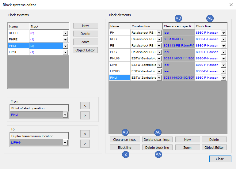
Illus.: Block elements with assigned Block line and clearance inspection
oWhen creating a block element, mark it in the list (B). After pressing the button 'Block line' (Z) the prompt 'Strecke wählen:' appears - In the drawing, select the area object line that passes through the Block element.
oThe Block route is a logical object that is assigned to the selected block element by the attribute 'Block line' (AE) and that is used to save the operationally relevant route data.
oThe Button 'Delete block line' (AA) deletes both the reference to the block route and the linked object Block route from the project.
12.The Clearance inspection can be performed with the button 'Clearance insp.' (AB).
oWhen creating a Block element, mark it in the list (B). After pressing the button 'Clearance insp.' (AB), the prompt 'Freimeldeabschnitt, FMA-Komponente oder Sensor wählen:' appears - Select the corresponding object in the drawing.
oThe Switching device is a logical object that refers to the object selected in the drawing with the attribute 'Control switch'. For the 'Clearance inspection (AD)', this has to be driven on and cleared. Further information on switching devices and their attributes can be found under Creating Switching Device(s) with the EPU Object Inserter.
oThe Button 'Delete clear.insp.' (AC) deletes both the reference to the object selected for the clearance inspection and the linked object Switching device from the project.