Creating Chainage Axis with the EPU Object Inserter

Contents
Process:
•Create Chainage Axis with the EPU-Object Inserter.
•Creating and deleting Chainage leap
Requirements:
•Creating Lines with the EPU Object Inserter
Description:
The Location of the Signalling elements can be determined automatically in ProSig. The requirement for this is the creation of the Area Objects Route and Chainage Axis, whereby the routes are defined. The Chainage information of a project is passed on according to the PlanPro scheme using automatically generated route points with the PlanPro-Export.
The Chainage axis is generated on the assumption of a previously created polyline, which represents the Chainage information. After creating the Chainage axis, the milestones are set automatically. The insertion or deletion of Chainage leap can be performed by selecting the Chainage axis from the context menu and right-clicking on it.
Procedure:
1.The Auto CAD PLINE function is used to draw one or more polylines that represent the Chainage information of the route.
2.Subsequently, a Chainage Axis can be created manually using the function EPU-Object Inserter. Select the Object type 'Chainage Axis'.
To create a Chainage Leap continue with Step 5.
To delete a Chainage Leap continue with Step 6.
To manually extend an existing Chainage axis continue with Step 7.
Command Line: PRS_EPU_EINF
Ribbon: ProSig EPU -> Equipment SCT-> EPU-Object Inserter
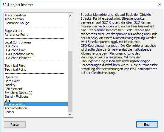
Illus.: Selection of the object type Chainage Axis in the EPU Object Inserter
3.With the button 'Paste' a new area object 'Chainage Axis' can be inserted into the drawing.
1.The Prompt 'Choose Polyline:' appears on the command line. - Select the polyline created in Step 1.
2.At the prompt 'Strecke wählen: [Prichtung]' the corresponding route object must be selected in the drawing (Layer PRS-STRECKE-<NAME>). For this purpose the corresponding route object must be created beforehand.
3.The Prompt 'Select end point of the polyline that corresponds with the smallest kilometer:' is displayed on the command line. - Select the end point of the polyline that corresponds to the starting point of the chainage axis.
4.At the prompt 'Enter start kilometer:' the start kilometer of the chainage axis must be entered. The value can be entered with up to 6 decimal places.
5.At the prompt 'Enter end kilometer:' a value for the end kilometer is automatically calculated based on the length of the created polyline. This value must be confirmed with the Enter key.
6.If a route to be kilometred is represented in the drawing by several polylines, steps 3.1 to 3.5 must be repeated for each polyline of this route.
oThe Chainage Axis is a PSO and is generated on the layer PRS-Chainage Axis-<LINE-NAME>.
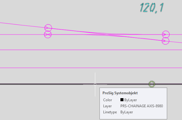
Illus.: Representation of the Chainage Axis in the drawing
oThe Milestones are automatically set in the layout plan at a distance of 100 meters. In overview plans, the distance between the milestones are set automatically to 500 meters. To align Chainage Axis in an overview plan, see also Alignment of chainage.
oThe labeling of a kilometer post can be moved separately in the drawing by marking the labeling and then Moving by Grips .
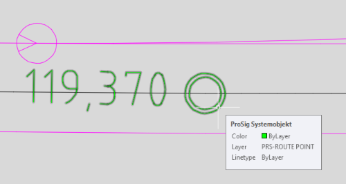
oRoute Points are automatically inserted at all points of the corresponding polyline, which are displayed in the drawing as green markers. Route points are PSO and are generated on the layer PRS-ROUTE POINT .
 |
 |
Illus.: Representation of a Route Point in the Drawing |
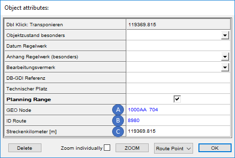
Illus.: Object attributes of a Route Point |
oThe Attributes 'GEO Node' (A), 'ID Route' (B) and 'Streckenkilometer [m]' (C) of a route point are automatically filled.
4.After inserting the Chainage axis, check all relevant data using the Edit Object(s) function.
Command Line: OE
Ribbon: ProSig EPU -> Tools -> Edit Object(s)
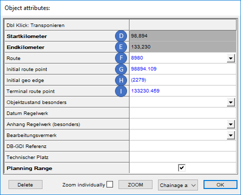
Illus.: Object Attributes of a Chainage Axis
oThe Attributes 'Startkilometer' (D) and 'Endkilometer' (E) are automatically assigned the values specified in Step 3.4 and 3.5.
oThe Attributes 'Route' (F) is automatically assigned and contains a link to the route specified in Step 3.2.
oThe Attributes 'Initial Route Point' (G), 'Initial Geo Edge' (H) und 'Terminal Route point' (I) are automatically assigned for the chainage axis and contain links to the corresponding objects.
5.To Create a Chainage Leap for a Chainage Axis, first mark the Chainage Axis in the drawing. Right-click to open the context menu of the Chainage Axis area object. Chainage Leap shall be inserted in ascending direction of the kilometer. A prerequisite for opening the context menu is the setting of the AutoCAD system variable PICKFIRST = 1.
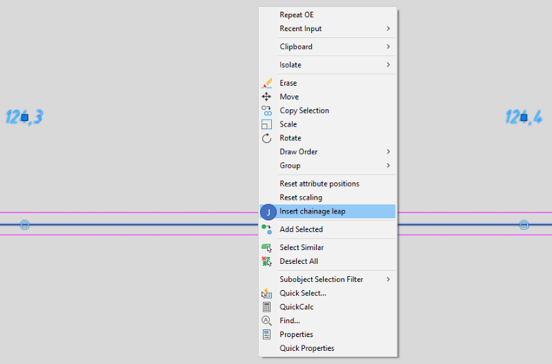
Illus.: Display of the context menu of the Chainage Axis - Insert Chainage Leap
1.Select the menu item 'Insert Chainage Leap' (J).
2.Enter the incoming kilometer for the Chainage Leap.
3.Enter the outgoing kilometer for the Chainage Leap.
oThe Milestones of Chainage Axis and its locations are automatically updated.
oThe Chainage Leap is part of the selected Chainage Axis and is stored on the PRS-CHAINAGE AXIS-CHAINAGE LEAP layer.
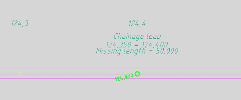
Illus.: Representation of a Chainage Leap in the drawing
oTwo route points are automatically inserted at Chainage Leaps.
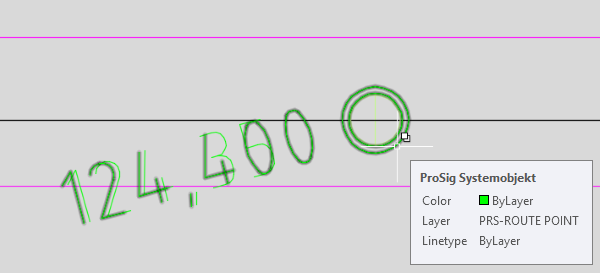
Illus.: Representation of the Route points of a Chainage Leap in the drawing
6.To Delete a Chainage Leap from a Chainage Axis, first select the Chainage Axis in the drawing. Then right-click to open the context menu of the Chainage Axis area object.
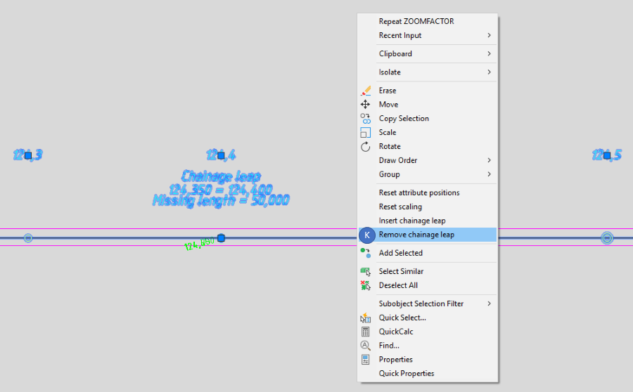
Illus.: Display of the context menu of the Chainage Axis - Remove Chainage Leap
1.Select the menu item 'Remove Chainage Leap' (K).
2.In the command-line the prompt 'Select chainage leap to be deleted:' appears with a list of the chainage leaps available for the selected chainage axis. The chainage leaps are numbered in ascending kilometers.
3.Specify the number of the Chainage Leaps to be deleted.
oDie Kilometersteine der Kilometrierungsachse und deren Standorte werden automatisch aktualisiert. Der gelöschte Kilometrierungssprung ist nicht mehr Bestandteil der Kilometrierungsachse.
7. To manually extend a chainage axis, follow the steps described below.
1.With the AutoCAD-Function PLINE, draw a polyline at the end of the chainage axis to be extended.
2.Then execute the function EPU-Object Inserter and select the Object type 'Chainage axis'. Press the Button 'Paste'.
3.Select the polyline from Step 7.1.
4.Select the corresponding route object of the chainage axis in the drawing (Layer PRS-STRECKE-<NAME>).
5.The following prompts will appear, depending on whether the chainage axis was extended at the beginning or the end. The new values for start or end kilometers are automatically determined based on the length of the polyline from Step 7.1.
▪The prompt 'Enter start kilometer:' is displayed with the automatically determined new start kilometer in the command line. The value must be confirmed with the Enter key.
▪The prompt 'Enter end kilometer:' is displayed with the automatically determined new end kilometer in the command line. The value must be confirmed with the Enter key.
oThe Attributes and display of the already existing chainage axis of the selected route are automatically updated and if necessary additional milestones are placed..