Planning Level Crossings - Basic Data

Contents
Process:
Planning a Level crossing with the Level crossing editor (Basic data):
•Creating a Level crossing system
•Creation of Track-related danger zones
Further information on planning a level crossing is provided under the following point:
Level crossings - Dependencies and Activations
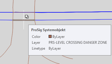
•Define the Level crossing at the track (see illustration) according to the Level crossing planning.
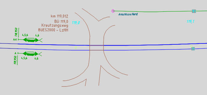
Illus.: Level Crossing on the Track
Description:
Plan the basic data for the creation of level crossings. Insert level crossing systems and define the track-related danger zones for a level crossing. In ProSig, the level crossing is a point object located on the topological edge. A track-related danger zone is an area object that is displayed at the topological edge and its boundary points are the intersection points with the crossing road or line.
In the PlanPro glossary, the corresponding objects are formulated as follows:
Level Crossing
Level crossing between rail and other land transport (e.g. motor vehicles, pedestrians, trams).
A Level Crossing (LX, Lx, occasionally LC) is protected by "technical protection" or "non-technical protection". In any case, St Andrew's crosses have to be arranged.
Technically protected level crossings receive a technical Lx Protection system consisting of a road traffic signal and if necessary, barriers. The associated relay room equipment is usually accommodated in a separate control station. According to Ril 815.0010, a technical protection also includes barriers.
Non-technically protected level crossings do not receive any further measures on the road/way side. If necessary, whistle boards and/or slow signals (Lf-Signals) are arranged for the rail vehicles or rolling stock.
The type and extent of Lx-Protection are shown in Table 1 in Ril 815.0010, Section 4.
Several danger zones can be assigned to the level crossing.
The Level crossing planning, which is regarded as a separate process, is integrated into the SCT data model via the Object Level crossing interface (BUE-Schnittstelle).
LX (BUE_Anlage)
A description of the structure of the level crossing (LX, Lx, occasionally LC), including the technical protection, if any.
At present, the information is limited to the part of the Lx to be represented in the layout plan. Later on the specific Signalling layout plan such as road traffic signal, St. Andrew's crosses, barrier machines, flooring in the level area etc. will be included in the model. The same applies to the power-on route calculation and the interference calculation.
The Object is located at the intersection point (in the middle of the crossing line or road); this results in the so-called Lx-Middle according to the strike-in distance calculation.
DB Rules and Regulations:
The following rules and regulations are applicable for the planning of level crossings:
•815
•819.12xx
The specific references to the set of rules are specified in the individual attributes.
Level Crossing Danger Zone (BUE_Gleisbezogener_Gefahrraum)
Area object that represents the danger zone of a level crossing for a track.
The Borders of the area object are located at the intersection point of the danger zone edge and the corresponding track.
The Corresponding switch-on and switch-off elements refer to the respective border of the area object. An object should be provided for each track on the LX. This means that a level crossing or a Lx-Danger Zone always has the same number of instances of BUE_Gleisbezogener_Gefahrraum as Lx-Tracks. If necessary, danger zone-specific information will be added at a later point in time.
DB Rules and Regulations:
•819.1210 7 (1)-(3)
(Source: PlanPro Glossary)
Supporting video sequence:
Planen_von_Bahnuebergaengen-Grunddaten.mp4 (Size 4,48 MB)
Procedure:
1.The Representation of the course of the road at the level crossing can be visualized through lines and arcs in the drawing at its actual location on the track.
2.To insert a new level crossing or to edit existing level crossing systems, start the Level Crossing Editor and select the 'Create' tab.
oThe insertion of a new level crossing is described in Step 3.
oTo select an existing level, continue with Step 4.
oTo edit the attributes of an existing level crossing, continue with Step 5.
oTo display existing level crossing danger zones for an existing level crossing or to Create new level crossing danger zones continue with Step 6.
oTo display and edit the attributes of a level crossing danger zone, continue with Step 8.
oTo delete a level crossing, continue with Step 9.
oTo zoom a level crossing in the drawing continue with Step 10.
oTo delete a level crossing danger zone, continue with Step 11.
Command Line: PRS_BUE
Ribbon: ProSig EPU -> Planning Basis -> Level Crossings
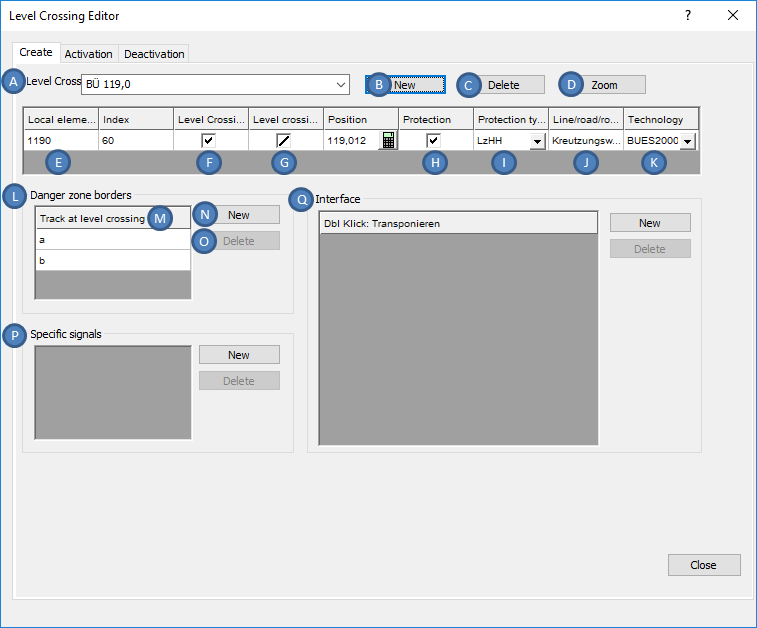
Illus.: Creation of a Level Crossing System with its Danger Zone Border using the Level Crossing Editor
3.In the section 'Level Crossing System' (A) a new object level crossing can be inserted into the drawing with the button 'New' (B).
oDuring the insertion, select a point on the topological edge (layer PRS-TOPOLOGICAL EDGE). As a rule, the insertion point should be the center of the intersecting line. The correct kilometer value can be found in the level crossing planning.
oThe Level crossing is a PSO-Point Object.
oThe Level crossing is a labeling object (see illustration below) whose insertion point is at the actual location of the level crossing. For a better overview of the representation, the level crossing can be moved visually and locally next to the track set using the object Grip.
oAfter the generation, the level crossing is displayed next to the track set and stored on the layer PRS-LEVEL CROSSING.
oThe newly created object level crossing is displayed with its attributes from the list of level crossing systems in the section level crossing system (A).
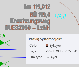
Illus.: Representation of a Level Crossing in the drawing
4.An existing level crossing can be selected for editing in the section 'Level Crossing System' (A) from the drop-down list.
5.For existing or newly created level crossings, the attributes can be edited from the list within the section Level Crossing System (A) or after closing the level crossing editor using the function Edit Object(s).
Command Line: OE
Ribbon: ProSig EPU -> Tools -> Edit Object(s)
 |
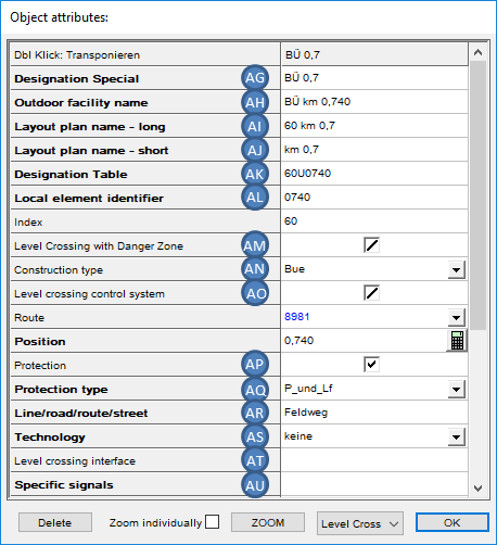 |
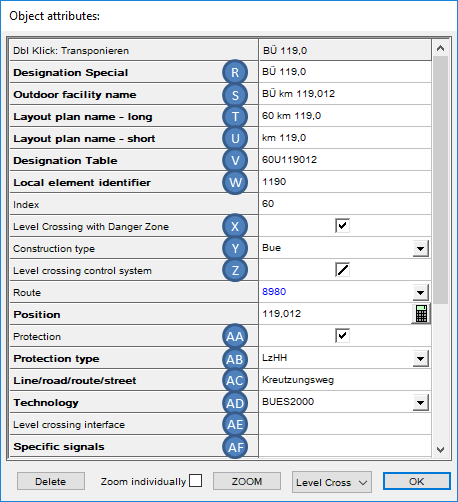
Illus.: Attributes of a Technically Protected Level Crossing |
Illus.: Attributes of a Non-Technically Protected Level Crossing |
oThe allocation of the attribute 'Local element identifier' (E, W, AL) needs to be specified according to the guideline mentioned in the tool tip.
oIf umlauts occur in the element identifier, then they should be entered in the attribute 'Designation Special' (R, AG) without code letters. (Ril 819.9001)
oFor the Attribute 'Outdoor facility name' (S, AH) the level crossing is designated with its actual station, which is attached to the concrete switch house: e.g. Level crossing km 119,012 (Ril 819.9001).
oFor the Attribute 'Layout plan name - short' (U, AJ), the level is designated with its position according to the stationing, but only with one decimal place: e.g. Level Crossing km 119,012 -> km 119,0. (Ril 819.9001)
oFor the Attribute 'Layout plan name - long' (T, AI) the specification is according to the guideline 819.9001.
oFor the Attribute 'Designation Table' (V, AK) the level crossing is designated with the ID number, with the ID letter 'U', and with the stationing according to the layout/overview plan, but without punctuation, for example level crossing km 119.012 -> 60U119012. (Ril 819.9001)
oThe Attribute 'Level Crossing with Danger Zone' (F, X, AM) should be activated, if the level crossing is monitored with a technical intersection train detection system (GFR). The GFR only takes place at level crossing with full barrier closure (two half barriers which together secure the entire road width (HH) or full barrier (V)). (Ril 819.1210) For editing check boxes see also Editing And Displaying Complex Data - Check box.
oThe Attribute 'Construction type' (Y, AN) needs to be assigned with the specification of the construction type of the level crossing according to the corresponding tool tip. (EPC: Ril 815, Resi: Ril 413)
oThe Attribute 'Level crossing control system' (G, Z, AO) should be activated, if the level crossing system is dependent on a road traffic light system at an adjacent intersection/junction. (Ril 815.0051)
oThe Attribute 'Protection type' (I, AB, AQ) provides information on whether a level crossing is technically protected or not (Ril 815.0010 4 (7) Table 1) The allocation is decisive for the specification of switching device(s), covering signals (using the level crossing editor, register 'Activation/Deactivation') or Specific signals (P, AF, AU) and the Level crossing interface (Q, AE, AT). This information is discussed in detail under Level crossings - Dependencies and Activations.
Protection Types for Technically Protected Level Crossings:
▪A + Lf,
▪A und Sprechverbindung,
▪Lz,
▪LzH,
▪LzH/F,
▪LzH/2F,
▪LzHH,
▪LzV,
▪Schlüsselabhängig
Protection Types for Non Technically Protected Level Crossings:
▪P,
▪P + Lf,
▪Ü,
▪Ü + P
An appropriate comment with explanations should be added for the entry 'Other'.
oFor the Attribute 'Protection' (H, AA, AP) the check box should be set to YES for technically protected level crossings and to NO for non-technically protected level crossings.
oThe Attribute 'Technology' (K, AD, AS) provides an information about the type of technical Level Crossing Protection.
▪For the technical protection, select the appropriate construction type for the technology from the drop-down list. (Project-related definition, not included in the rules and regulations. General information under Ril 819.1203 2)
▪For non-technical protection of the level crossing, the value 'None' should be entered in this field.
▪An appropriate comment with explanations should be added for the entry 'Other'.
oFor the attribute 'Line/road/route/street' (J, AC, AR) the following specifications are permissible (DB Rules and Regulations: 'Password' in the strike-in distance calculation):
▪Name of the intersecting Line or road or route or street.
▪Concise designation of the level crossing based on the locality or area in which it is located.
6.To Create or display the track-related danger zones for a level crossing, first select the corresponding level crossing in the section 'Level Crossing System' (A). Any existing Level Crossing danger zones are displayed in the section 'Danger zone borders' (L) within the list 'Track at level crossing' (M).
7.To create a new Level Crossing Danger Zone to the marked level crossing, press the button 'New' (N) in the section 'Danger zone borders' (L).
oDuring the insertion of the level crossing danger zone, the following boundary points are used
▪The Intersection point of the crossing road with the topological edge (layer PRS-TOPOLOGICAL EDGE) or
▪The Reference Points previously inserted at the boundaries of the level crossing danger zone
to choose. Exit the selection with the Enter key.
oThe newly created level crossing danger zone is displayed with its attribute 'Track at level crossing' in the corresponding list under (M).
oThe Level Crossing Danger Zone is a PSO-Area Object.
oAfter the creation, the level crossing danger zone is displayed on the track set and stored on the layer PRS-LEVEL CROSSING DANGER ZONE.
Illus.: Representation of Level Crossing Danger Zone in the Drawing
8.After the insertion of a Danger zone border, the attributes can be edited using the function Edit Object(s) once the level crossing editor is closed.
Command Line: OE
Ribbon: ProSig -> Tools -> Edit Object(s)
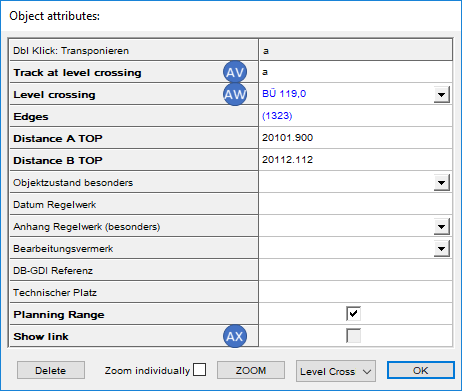
Illus.: Attributes of a Level Crossing Danger Zone
oThe Attribute 'Track at level crossing' (M, AV) is automatically assigned with the value 'a' and if necessary it can be manually adjusted. It represents the name of the Level Crossing Tracks. The name is assigned in alphabetical ascending order, starting with 'a'. (The Planning date is derived from the input sheets of the strike-in distance calculation)
oFor the Attribute 'Level crossing' (AW), when the level crossing danger zone is created using the level crossing editor, a reference to the corresponding level crossing is automatically entered. This reference can be adjusted as follows:
▪1. Possibility: Select the corresponding level from the drop-down list.
▪2. Possibility: Right-click in the value field of the attribute 'Level Crossing' to open the context menu, select the menu item 'Assign object' and select the corresponding level crossing object in the drawing and confirm your selection with the Enter key.
oBy activating the attribute 'Show link' (AX), the connection between the level crossing danger zone and the superior level crossing is visualized in the drawing.
9.The Button 'Delete' (C) is used to delete an existing level crossing that has been previously selected in the section 'Level Crossing System' (A) from the drop-down list. The associated objects 'Danger Zone' are automatically deleted as well.
10.The Button 'Zoom' (D) is used to mark and zoom a level crossing of the drawing which is selected from the drop-down list.
11.The Button 'Delete' (O) is used to delete an existing danger zone which has been previously selected from the list 'Track at level crossing' (M).