Editing And Displaying Complex Data
When editing and displaying attributes with the functionalities
•Edit Object, Edit Object(s) and Edit Object Type in ProSig CAD
•Edit Object Type Tables in ProSig Engineer
The following information may be helpful:
It is possible to have the value of an attribute calculated automatically. In this case, a button with a red exclamation mark is displayed at the right edge of a value field.
 Illus.: Attribute can be calculated automatically, using the example 'Nominal Length [m]', Object Type Overlap Press the button to write the calculated value into the value field. If the value in the value field corresponds to the calculated value, the image on the button changes to a check mark.
 Illus.: Attribute after the automatic calculation using the example 'Nominal Length [m]', Object Type Overlap The calculated value can be adjusted by the user (as described under Override of automatically calculated Values). If the value in the value field does not correspond to the calculated value, a red exclamation mark is displayed on the button.
 Illus.: Attribute after customization, using the example 'Nominal Length [m]', Object Type Overlap Objects can also be assigned automatically. A button with a red exclamation mark is also displayed on the right side of the value field.
 Illus.: Attribute can be calculated automatically, using the example 'Destination Track Section', Object Type Overlap After pressing the button, the associated object is automatically assigned. If the value in the value field corresponds to the calculated value, the image on the button changes to a tick.
 Illus.: Attribute after the automatic calculation, using the example 'Destination Track Section', Object Type Overlap Automatically assigned objects can be adjusted by the user (as described under Assigning Objects). If the value in the value field does not correspond to the calculated value, a red exclamation mark is displayed on the button.
|
Attributes that are relevant for the representation of a PSO or that are displayed in the drawing are usually displayed in bold type in the dialogs for editing the object attributes.
After editing such an attribute, the relevant PSO is automatically updated in the drawing after closing the dialog (e.g. attribute 'Type of Controlling' of object type 'Switch element' or attribute 'Type' of object type 'PZB-Element'). |
Fixed prescribed values are offered in drop-down lists in order to avoid incorrect or ambiguous entries and to enable programmatic evaluations.
The structure of the dropdown lists varies depending on the value to be displayed. The list elements can be fixed default values that must be available in a prescribed format, e.g. for data exchange with other systems or for programmatic evaluations.
However, the list elements can also be linked objects that can be Assigned to this attribute. Objects are listed in the dropdown list primarily by object type and secondarily alphabetically.
This results in the following options for the composition of the elements in the dropdown lists of the object attributes:
oThe dropdown list contains only default values as selection options (e.g. 'Type' attribute in the 'Track Route' object). To export the planning data effectively, you must assign one of the values from the list.
oThe dropdown list contains default values and an empty entry as selection options. The empty entry cannot be edited and can have the following meanings: ▪An empty entry has the meaning of an entry, e.g. the attributes 'Track Vacancy Section Limit 1' to 'Track Vacancy Section Limit 4' for the object 'FMA Component', and is evaluated accordingly in the program.
▪Empty entry means 'no entry' or 'no assigned object'. oThe dropdown list contains linkable objects as selection options (e.g. attribute 'Reference Point' in object 'FMA Component'). The corresponding object must be created beforehand.
With the delete key, filled values can be deleted from the field at any time. |
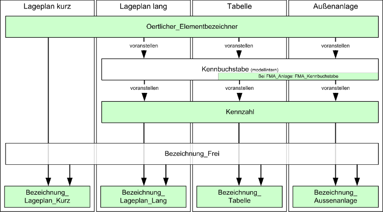
The identifiers of an operable element is usually the element name. The layout plan usually uses the short name (mostly local element identifiers). The long name (usually element name) is used when there are several ID numbers in the selected section. However, there are a number of exceptions that can be different for outdoor facilities, layout plan and table. In order to avoid discrepancies, the resulting identifiers for outdoor equipment, layout plan and tables are stored.
The algorithm for forming each identifier of an element is shown in the following image.
(Source: PlanPro glossary)
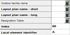
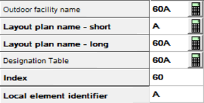
For identifiers (for example for the identifier of elements outside the CBI (legacy technology)), the automatically calculated value can be overwritten (as described in Override of automatically calculated Values). The corresponding identifier will not be updated when the attribute 'Local Element Identifier' is adjusted. |
Information of an attribute can be found in the description in the corresponding tooltip. The tooltip is displayed by holding the mouse cursor over the corresponding attribute for a short time. |
For automatically calculated values (e.g. object identifiers or location) it is possible to overwrite them manually.
Overriding of automatically calculated values using the example location: If the location is not entered automatically when inserting objects, it is possible to have the value of the attribute determined automatically, provided that a chainage (PSO Area Object distance and chainage axis) is present at the insertion point of the object and the attribute 'Route' of the inserted object has been filled. In this case, a button with a calculator is displayed at the right edge of the value field.
If the Import the PlanPro XML, the attribute 'Location' of the imported objects is automatically overwritten with the value from the PlanPro XML and the image on the button changes to a pen.
 Illus.: Attribute 'Location' was overwritten |
A linked object is a PSO referenced by the attribute of another object.
If the linked object is the element of a Drop-down list, the context menu can be activated by right-clicking and the object attributes of the linked object can be displayed via the Menu item 'Show link object'.
If it is not the element of a drop-down list, the attributes of the linked object can also be opened by double-clicking on the value field. |
In ProSig CAD, after selecting a value field in the object attributes and then zooming in using the 'ZOOM' button, the object in the drawing is zoomed. If the selected value is a Linked Object, the linked object is zoomed instead.
It is also possible to zoom several objects one after the other or simultaneously. If the Check Box 'Zoom individually' is activated, the selected objects are zoomed one after the other. By pressing any key the next object is zoomed.
You can select several value fields by pressing the 'Ctrl' key and simultaneously selecting the corresponding fields with the left mouse button. |
In ProSig projects, direct relationships between objects can be created starting with version 7 EPU. To do this, you can refer to other objects in the object attributes of an object, see also Linked Object. Depending on the type of reference, one or more objects can be assigned to a attribute. Value fields of attributes that contain object references cannot be edited manually. An object can be selected via the context menu, in some cases a (Drop-down list) is available for selecting the object.
1.Opening the attributes using the Edit Object(s) function, e.g. the attributes of a fouling point marker. Command Line: OE Ribbon: ProSig EPU -> Tools -> Edit Object(s)
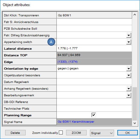 Illus.: Attributes of a Fouling point marker
2.Open the context menu by right-clicking in the value field of the attribute to which one or more objects are to be assigned, e.g. in the value field of the attribute 'Appertaining switch' (A).
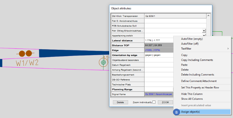 Illus.: Open the context menu by right-clicking in the value field.
3.Select the context menu item 'Assign object(s)' (B) in the context menu. oDepending on the type of reference, one or more objects can be selected in the drawing.
4.Select one or more objects in the drawing. Exit the selection with the Enter key.
5.The attribute 'Appertaining switch' (C) is updated.
 Illus.: Assigned switch in the 'Appertaining Switch' attribute of a fouling point marker |
For the assignment of Assign dialog objects the general description as described under Assigning Objects applies. The assignment of objects via the dialog can be done either via the object attributes or with the following functionalities:
oAssigning attachments to the project object, e.g. using the Edit Project Object function oAssignment of Standard drawings to the signal, e.g. via the function Signal - EPU oAssignment of signals in the INA attributes, e.g. via the PZB/INA Editor function
Assign dialog object(s) - Procedure (using the standard drawing of a signal mount as an example):
1.Open the attributes using the Edit Object(s) function, e.g. The Attributes of a signal mount. Command Line: OE Ribbon: ProSig EPU -> Tools -> Edit Object(s)
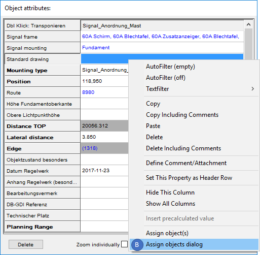
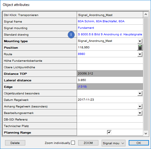
 Illus.: Attributes of a signal mount 2.Open the context menu by right-clicking in the value field of the attribute to which one or more objects are to be assigned, e.g. here in the value field of the 'Standard drawing' (A).
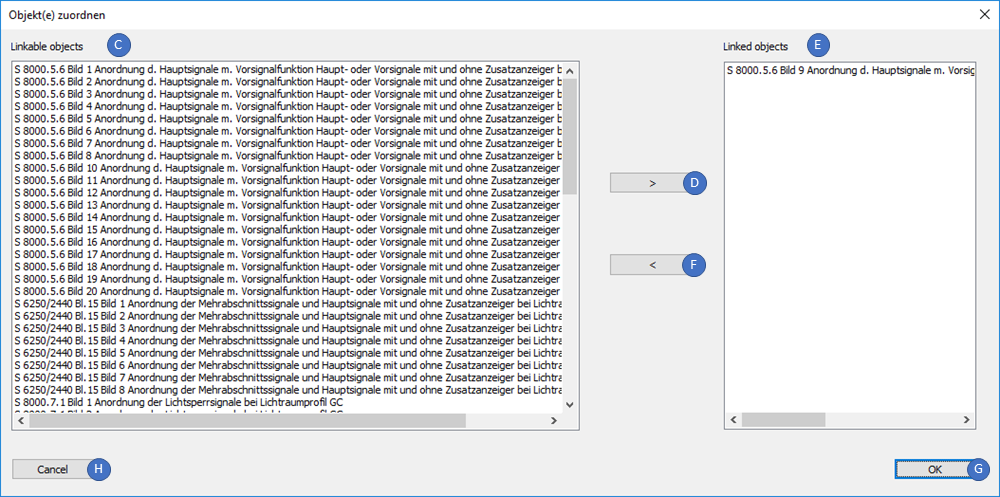
3.In the context menu, select the context menu item 'Assign objects dialog' (B). 4.Select one or more standard drawings in the list 'Linkable objects' (C) and transfer them to the list 'Linked objects' (E) via the button '>' (D).
oAfter selecting one or more assigned objects in the 'Linked objects' list (E), the assignment can be removed using the button '<' (F). The standard drawing is then displayed again in the list 'Linkable objects' (C).
oWhen leaving the dialog with the 'Cancel' (H) button, the adjustment made in the dialog is not carried out. 5.The attribute 'Standard drawing' (I) is updated after closing the dialog via the 'OK' button (G) and pressing the 'F5' Button. |
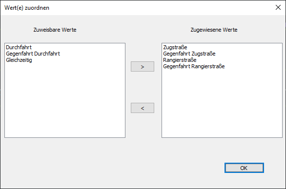
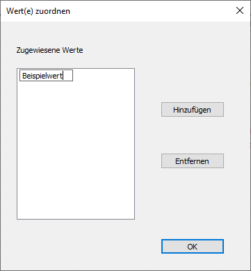
Für einige Eigenschaften besteht die Möglichkeit, Werte zuzuweisen. Hierbei ist zu unterscheiden, ob es sich um einfache Textfelder handelt und somit eine freie Texteingabe zulässig ist oder ob nur bestimmte Werte zulässig sind. Das Zuordnen von Werten kann durch Aufschalten des Kontextmenüs über Rechtsklick und Auswahl des Kontextmenüpunkts 'Wert(e) zuordnen mittels Dialog' vorgenommen werden.
Prinzipiell können auch mehrere Werte zugeordnet werden, die mit | getrennt in das Feld eingetragen werden. Das Zuordnen mehrerer Werte führt beim Export einer PlanPro-Datei jedoch ggf. zu einer nicht mehr validen Datei und sollte in Planungen, bei denen als Ergebnis eine PlanPro-Datei gefordert wird, nicht durchgeführt werden.
oBei Dropdownfeldern oder einzelnen weiteren Eigenschaften (z. B. die Eigenschaft 'Fahrstraßenpfeile' im Freimeldeabschnitt) können nur die fest vorgegebenen Werte eingetragen werden. Nach dem Schließen des Dialoges über die Schaltfläche 'OK' wird der/die zugewiesene/n Wert/e in der Eigenschaft eingetragen.
oBei allgemeinen Textfeldern können beliebige Werte definiert und eingetragen werden. Nach dem Schließen des Dialoges über die Schaltfläche 'OK' wird der/die zugewiesene/n Wert/e in der Eigenschaft eingetragen. |
Für einige Eigenschaften besteht die Möglichkeit, neue Objekte erzeugen zu lassen und automatisch den Verweis auf das neu erzeugte Objekt einzutragen. Dieses kann durch Aufschalten des Kontextmenüs über Rechtsklick und Auswahl des Kontextmenüpunkts 'Referenzwert(e) erzeugen und zuordnen' vorgenommen werden. Das beschriebene Vorgehen kann verwendet werden für den Verweis auf ein oder mehrere logische Objekte, die nicht in der Zeichnung dargestellt werden. Beispiele hierfür sind das Festlegen von Datenpunkt-Typen oder das Erstellen und Zuweisen von Balisen bei der ETCS L2- und ZBS-Planung. |
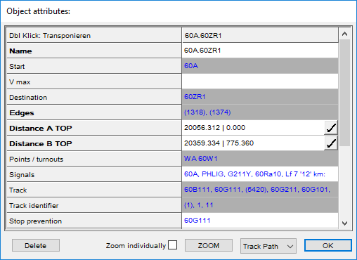
For a composite attribute, the value contains several other attribute values. For example, the value of the attribute 'Name' of the track path results from the values of the attributes 'Start' and 'Destination'. |

